Collins 75A2 s/n 71
for full description and specs for the 75A2 go
to:
http://www.wa3key.com/75a2.html
click on thumbnails for full-size view
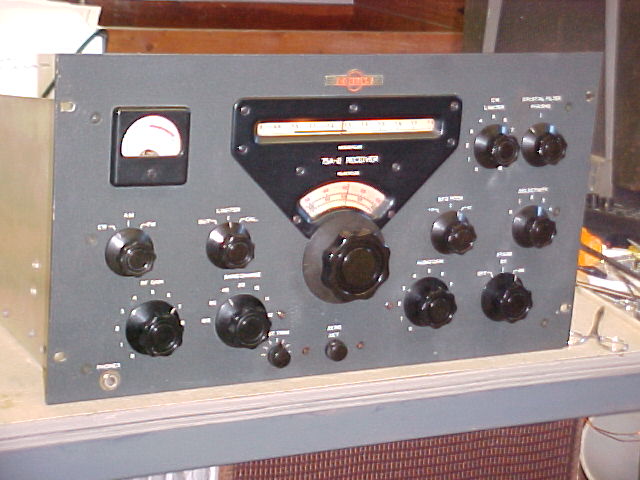
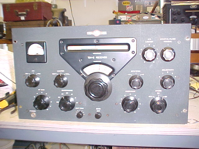
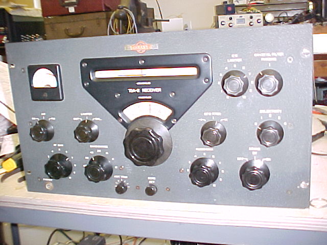
After cleanup, this receiver looks very nice. Knobs were soaked in soapy solution, brushed clean & waxed. The front panel is in very nice condition. The cabinet was not cleaned.
Original inspection revealed that the dial calibration was way off, as noted in the PTO section below. AVC didn't seem to be very active, as the S-meter would only deflect on very strong signals, maybe a general sensitivity problem. There was also a "warbling" on signals, SSB couldn't be tuned in to give clear audio. Wiggling V-14 on the PTO seemed to aggravate the condition. All tubes were removed and checked, one 6BA6 tested poor and was replaced. Tube pins were cleaned with a brush, straightened, and treated with DeOxit at replacement. Signal stability was still a problem.
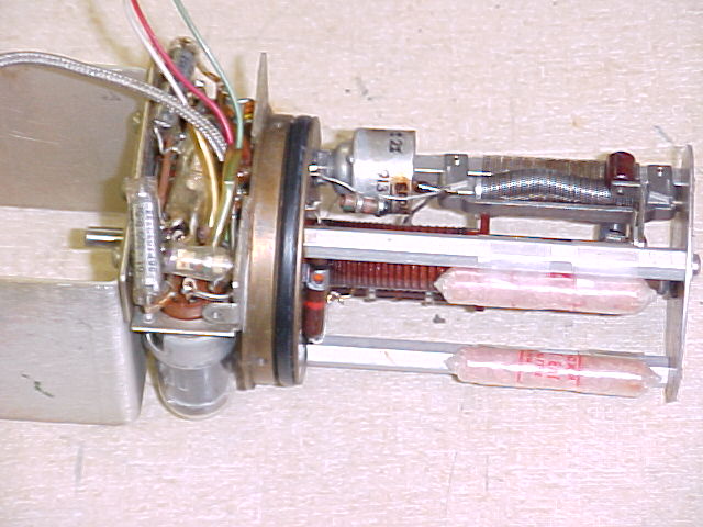
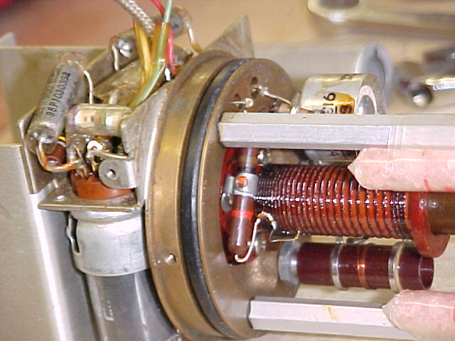
PTO repair
This PTO had very poor calibration, the dial
adjustment couldn't be moved far enough at either end of the frequency
range. An indicated 1000kc change resulted in an actual change of about
974kc, a 26kc shortcoming. Removal of 2 turns from the compensating coil
reduced the error to about 12kc. Normal adjustment of the dial pointer allows
about 6kc error at each end of the range, our 12kc total is barely within the stops on the
adjuster. The stops can be (were) relocated to allow about 2kc more on each end.
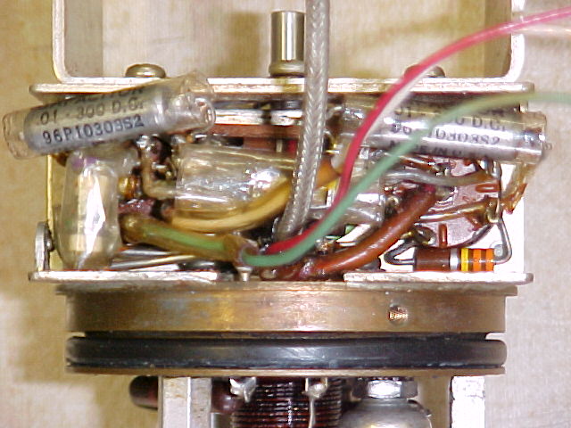
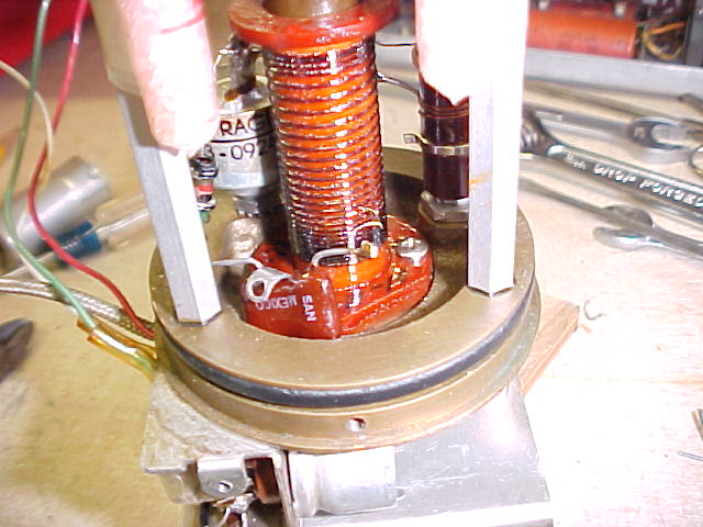
As preventive maintenance, it is always a good idea to replace the 2 bypass
capacitors and the one feedback cap in the PTO while it's open. This was
done.
While on the bench, the "warble"
problem was resolved. By watching to PTO output signal and wiggling V-14
it was determined that the source was there. Resistor R-127 is 1000 ohms,
and feeds the plate of V-14. It was cracked, and would go open when pin 5
of V-14 was moved. It was hidden under bypass cap C-132, was invisible
when the original cap was in place, and almost invisible when the new, smaller
cap was installed. It was replaced, received signals are now very
stable.
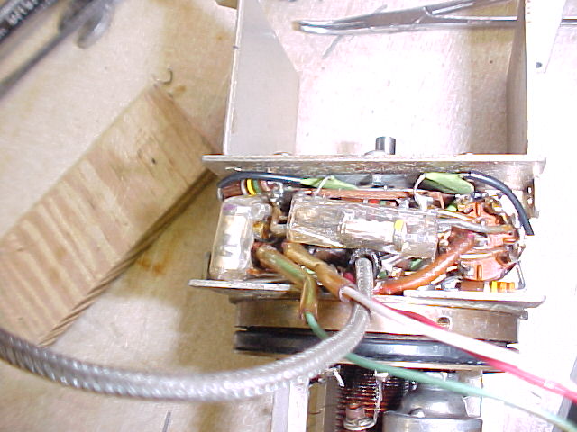
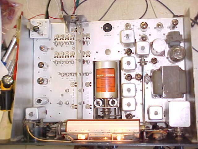
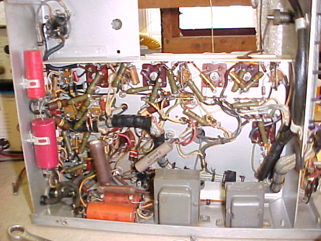
bottom
view
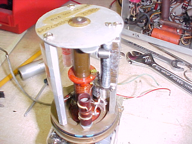
top
view
orig.
bypass caps replacements
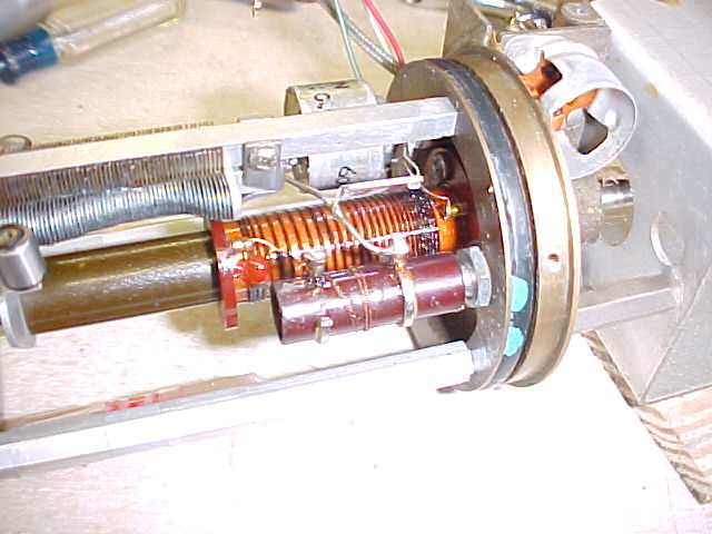
orig. fdbk cap.
new fdbk
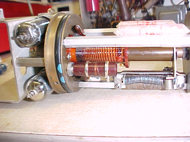
cap comp.
coil comp coil, less 2 turns
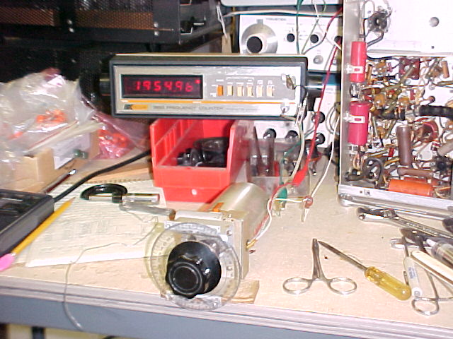
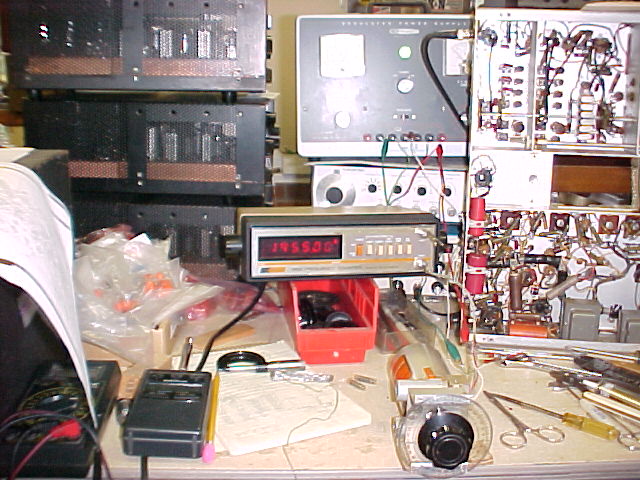
test setup freq. ctr
& p.s. in bkgnd
General repair items
All electrolytic capacitors were checked for ESR (Equivalent
Series Resistance). The power supply filters, dual 40mf in one can,
checked at 0.27 ohms, very acceptable for their size and voltage ratings.
The 50mf in the bias supply line was 0.50, only fair for it's low voltage, and
the 20mf in the AVC amp. ckt was 91 ohms, BAD. The latter 2 were
replaced.
Besides the 3 in the PTO, 3 other capacitors
were replaced, C-74, C-90, C-100. 2 can affect the AVC, and one was at the
CW Noise Limiter.
One dial #47 lamp was burned out &
replaced.
This receiver did not have a crystal calibrator when
it arrived. I modified the plug on a Heath Calibrator, installed a 100kc
crystal, and installed it. It may interfere with the back panel of the
cabinet, as it sticks out about 1/8" from the back of the chassis. It
makes the dial accuracy much less of a problem, as it is within 1kc between
100kc points.
Replaced 2-wire AC line cord with
3-wire, and added 2 .01@240vac capacitors to
ground.
Alignment
The 455kc IF was quite a way out, signal peaked up a lot at each adjustment. The variable IF's, 2.5 - 1.5kc and 5.455 - 3.455kc, were fairly close, only small adjustments necessary. All RF bands were very close, only slight adjustments necessary in the coil slugs. Most of the variable trimmer caps were stuck, and since the coils were so close, I didn't risk breaking anything and didn't apply force.
After alignment, and adjustment of the S-meter zero (adj. pot is noisy), reception of signals improved greatly, and S-meter action is normal. I can listen to 14.300 SSB, the Maritime Net, all afternoon without making any adjustment other than RF gain. After turning it off all nite & powering up again it was less than 1kc off frequency. Not bad for a 50 year old receiver.
As Sergeant Preston said to his trusty dog, King, "well King, I think this case is empty." I think I'm done with this one, 10/16/03.
Radio to see home page
comments to anchor@ec.rr.com
And remember: "They don't make tubes nowadays like they used to..."