I received this picture & the letter below, from
Edgardo, YS1ECB, a Physics Teacher at the American School of San Salvador.
He's particularly interested in obtaining a schematic, and
any other tech. info, on the DF eqpt that's on top of the speaker. Any help you
can give him would be greatly appreciated. He's also about to start
restoration of a Hallicrafters SX-25, some info on it is at the bottom of the
page.
thanks for your help, 73, Al, W8UT (May 2002)
(he did receive information, thanks to some of the "boatanchor"
guys) (Sept. 02)
He is now in need of the 2-section gain control for the
BC-348, he may be contacted at mailto:castrobruse@yahoo.es
(3 Sept 02)
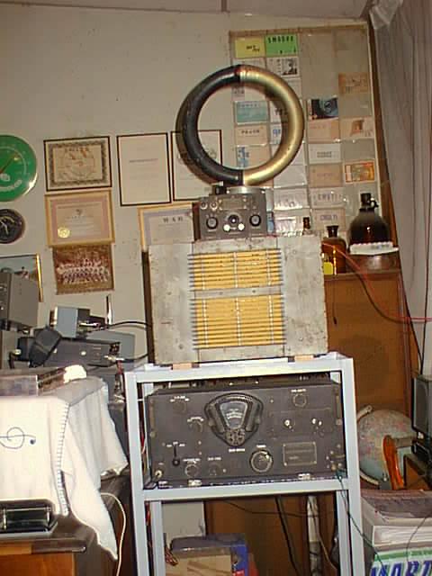
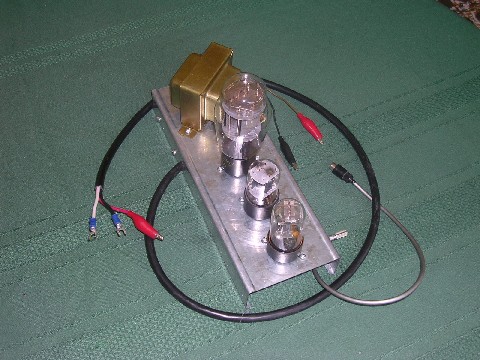
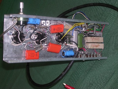
I bought a BC 348-Q along with a direction finder model DU1 made for the Navy
Department Bureau of Ships By Bendix Radio. It comes in a box that is
called Coupler Unit Type CRR 50061 by Bendix Radio.This box contains a Low
Frequency Preselector that carries the signal picked up by the loop antenna into
the antenna terminal of the BC-348-Q.
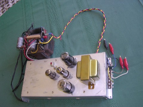
The entire set up works excellently. I still need to do some
minor adjustments. I am sending as an attachment the picture of The BC-348-Q and
the direction finder. You will recognize that the direction finder is on
top of the PM 23 Speaker. inside this box is the original loud speaker
which works super well. You will see how badly it needs to be painted.
I already cleaned and repaired the BC-348-Q.
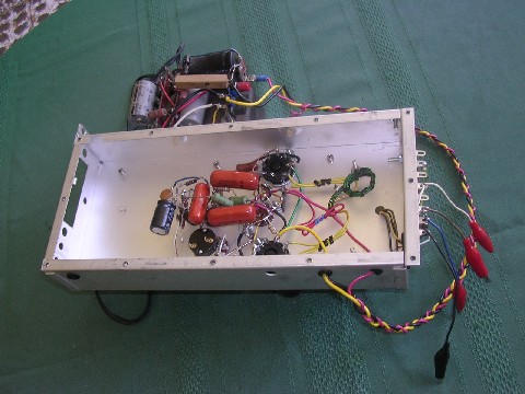
The BC-348 and its direction finder and preselector is
the best find I have ever
made. The entire apparatus shown in the pictures were semi buried for more
than a year as result of the earth quake that devastated different location in
YS Land. Those apparatus belonged to an old timer that actually made Radio
goniometry with this set up.
If you can help me get the manual for the direction finder I
will appreciate very very much.
Best 73s. Edgardo
Please email to: castrobruse@yahoo.es
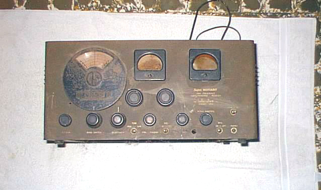
SX-25
Hello Al,
Thanks for writing today .
I spent some time today
evaluating the damages in the SX-25.Besides the physical evidence, I found that
the three section electrolytic condenser has been replaced by only a two
sections one ,and consequently the circuit has been modified a little bit. But
no problem I will put it back to the original way.
The half of Primary of the pp audio output
transformer is open. Here there is no problem because I have one that will
work.
Here comes a somewhat major problem the
primary of the 6 K8 IF transformer (T1) is also open. Luckily the
secondary which is more complex is OK.
Since I think this is the only SX-25 in the
country my alternatives are :
First: Remove the secondary winding and replace it by another winding of any other 455 KC IF transformer that has the same diameter so I can slide it over the form of T1 .
Second: find if anyone here has a machine to make a honeycomb winding and get the winding made. 3rd to use any tube type IF transformer for 455KC. in which case i will lose the functioning of the selectivity control. and finally that you can help me to get an original SX-25 T1 IF transformer.
Also some of the paper
condensers will have to be replaced along with some resistors.
The DB meter will need the plastic
lens to be replaced as well as the band spread lens.
Well , I will keep you informed of
how the restoration is going along.
When I get to the cabinet I will need a great
deal of help related to the lettering and the alike.
I need to do some repairs to my 20 meter
antenna. As soon as I make them I will let you know so we can also talk over the
radio once in a while.
Best 73 s Edgardo.
Please email to: castrobruse@yahoo.es
Later he reported:
This evening
about 3.30 PM The SX- 25 Spoke once again ,after probably 40 or more years, in a
magnificent way!!
I replaced the PP
Audio transformer that had half of its primary open by a 10 watt model A-3839
Chicago Standard Transformer Corporation transformer that had been given to me
several years ago by YS1AG.
This transformer Has
a 500 ohms sec. as well as 4 , 8 ,and 16 ohms taps. The only modification I
had to do was that the 4 ohms tap was connected to the rear 5000 ohms connection
strip and will not be
interrupted by the earphone jack at the front panel. This was necessary to
avoid leaving the transf.
secondary without speaker when a high impedance earphone is plugged into this
jack. The 500 Ohm tap was connected at the appropriate rear connection
strip.
The sound is super
good !!.
To make the test I removed all tubes but the ones that form the audio amplifier
.I did this to avoid problems
with the 6K8 IF transformer that is open ( precisely The plate coil).
and later---
Well I am very happy that
rewinding the primary of T 1 worked so well.
I unwound the coil with
the hope that the cut would have be at the beginning, but for my surprise it was
almost at the end of the coil.
So I got a plastic tube that
would fit the T 1 form And cut it at a length of about one inch and wound the
coil on it I cover it with wax and then slipped it on the T 1 form. To fix it
there I put some candle wax.
Without the shielding on T1 I move the band SW to
1 and turned the SX-25 ON Almost immediately a strong local BC Station came
in!! I readjusted the IF trimmer of the new winding and the station
was even louder.
Then I put the can over and try the Short Waves nothing
came in. I tried it again at night with my inverted L and all Short wave bands
worked. So I only need to properly align the IF and RF circuits to finish the
electronic part.
He is still (3 sept 02) waiting to get some good pictures of the front panel of the SX-25 so he can re-letter it properly. (One ham has offered, but is on extended vacation until late Sept.)
Much later, in August 2004 he writes:
Hello Al.
I am still battling the SX-25.I have discovered something unusual, the
primary of the second IF transformer when measured with my digital multimeter in
the Ohms position registers infinite resistance, like an open circuit.
Nevertheless when I measure the voltage at the plate of the 6SK7 it is connected
to, the voltage is normal.- the voltage at the other end is within it expected
value. So it seems to me that conductivity is achieved only when 280 V DC are
applied. But this conductivity is very marginal, but the set still works
nearly as expected except in Band #4. This explains the relatively high
noise .like static discharges even when there is no antenna connected to the
receiver. I will open the IF can and I hope it is only a cold solder
inside. I notice that the circuit about this IF has been tampered since I
notice that there is a wire that has been cut near this IF can. This was
difficult to detect because such wire was underneath another wire that ran on
top of it.
Well Al, I do hope this will not only quiet the receiver but should help
in the actual gain in band #4 since the signal to noise figure will be improved
and the gain itself should be more.
Best 73 s.
Edgardo.
and a few days later:
Hello Al,
I am very happy I was able to fix the IF transformer. As you know these
transformers have 2 ceramic trimmers on top ,well a wire that connects the
trimmer with one end of the primary and the plate of the 6SK7 was making contact
basically by gravity and the current flew by arcing between this wire and the
coil end. It was close to brain surgery because the coil end was a piece
of coil wire about 2 or 3 mm long. After soldering it. I put
together the IF can and solder it in place.
The results were great. In Band no. 3 I moved to 14 mc. And I
was able to tune a good No. of SSB ham stations. I am amazed with the
clarity the stations were coming in using the BFO. I moved to Band 4 the
bad one, and I was able o tune some station . About 18MC I came across a station
that sounded like some kind of CW with a steady tone. I used this Stn. to
peak the IF can I just repaired. It responded real well. And I was able to
pick up some Stns in a decent way for the 1st time. I then went back to
Band 3 to 14 mc. and to my surprise I was able to hear many many SSB Stns.
I then I focused on the regular BC stns. and it behaved super well. Now this
receiver is beginning to honor Mr. Halligan.
Well AL, I do feel real well and I will tell you latter when I make more
improvements.
Best 73s.
Edgardo .
and a few days later:
This radio has demanded lots of work and time. It also has a mechanical
problem that. As you know the main tuning condenser is acted by a
reduction mechanism; well, the teeth of one of toothed wheels are somewhat worn
out and this results in a kind of back lash. Luckily it is possible to
disassemble the mechanism in order to change the worn out piece. Now that
the receiver is working real well I think it is worthwhile doing it. I do
have a friend that could make this piece. Unfortunately in this part of the world, homes
don't have a basement, so I do my repairs next to my "studio or radio
shack". I could do my repairs in my radio room ,but my children, that
still live at home, have the computer and associated gear in it.
Bueno asi es la vida!!!
Best 73s.
Edgardo .
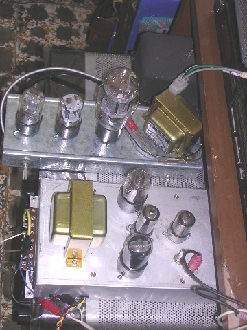
In January, 2004, Edgardo sent me this picture of him in his shack.
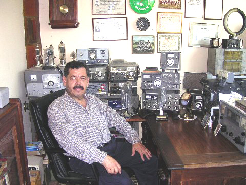
and some of his audio amplifier projects using 421A & 6AC5 output tubes.
email to anchor@ec.rr.com
And remember: "They don't make tubes nowadays like they used to..."
This page last updated on 08/14/2004.