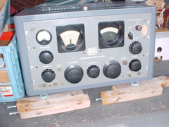
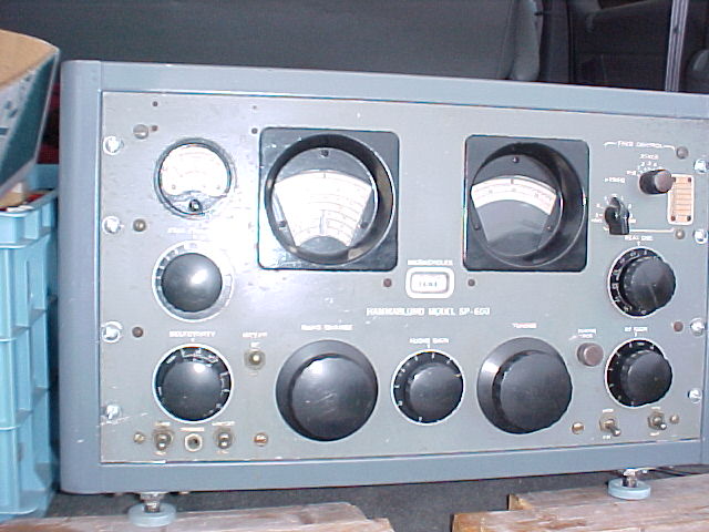
SP-600-JX-14 s/n 9386
8/30/04 pix & comments on "as received" condition. click on thumbnails for full-sized pix
Cabinet paint good in general, some small nicks/scratches. There are slide rails on the inside of the cabinet, but no matching parts for slides on the chassis.
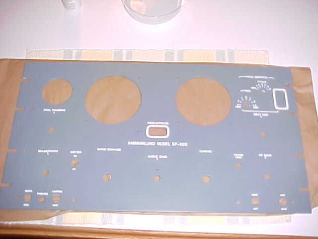
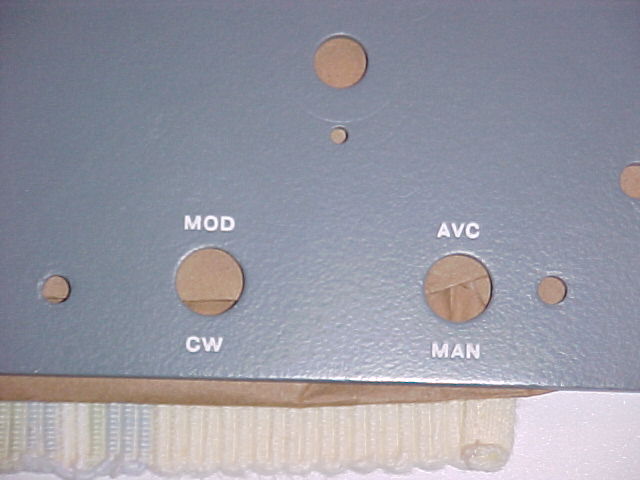
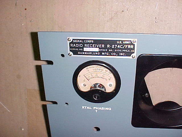
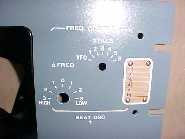
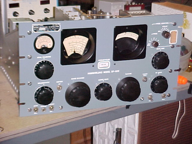
"hardware store" rack screws, rd head slotted, w/flat washers, cad plated. Front panel is dirty, some corrosion pits in & under paint, some scratches, usual scars at rack-mnt slots. Only 4 of 10 panel screws are orig., I can install orig. type pan head slotted in SS. All large knobs are there, no chips, gouges, etc, & should clean up OK. The "FCU" knob is not original, nor is the "Mod/CW" switch. The dial bezels may have been painted, the finish is not as smooth as original. The R-274 ID tag is missing from the top left of the panel, 4 screws are there. A repro. can be purchased, with whatever s/n desired.
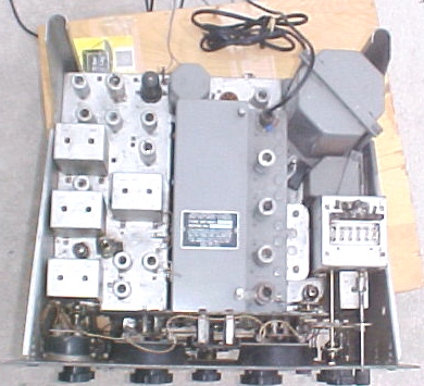
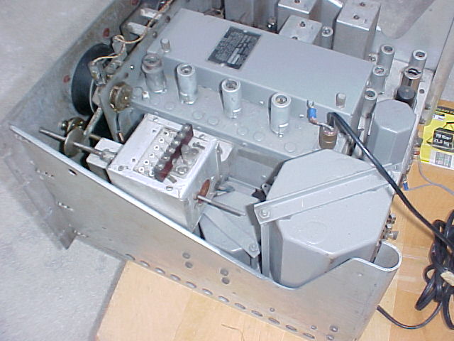
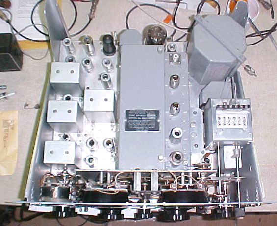
Top of chassis is dusty/dirty, and will show some blemishes when cleaned. The top of the RF deck, and the tuning cap. cover have been painted gray, as have the power xfmr & audio output xfmr. The steel RF deck may look better this way than if it was stripped as the pitting in it is probably too bad to polish out. The tuning cover is aluminum and could be stripped & should come up fairly shiny. 2 allen wrenches are in place in 2 of the 3 slots in the holder clips, there's an extra toggle switch mounted in between V-6 & V-9, function unknown at this time. Missing items: tube shields for V-9 & V-13, hold-downs for V-17 (6V6) and V-19 (5R4GY), V-19, V-3 (6AC7 in FCU), all 6 xtal clamps are broken off the holder on the FCU. 4 extra fuses are in place, but the plastic cover is missing (screw is there & bit of plastic). There is a wire w/RCA plug connected to 600 ohm audio output terminals for external spkr, there's a section of RG-58 with the 2-prong coax antenna connector (small chip in insulator). ( and SO-239 "std" coax con. can be installed when RF deck is serviced if desired.) All hole covers are in place on the RF deck & "pod" (painted gray).
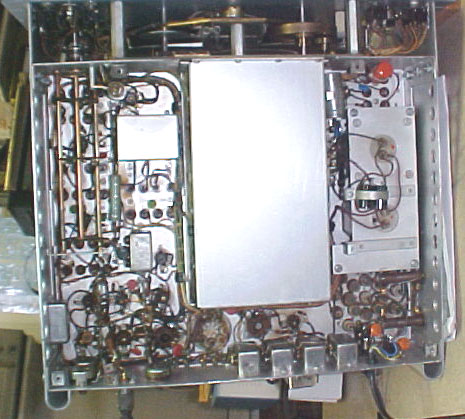
There is a bottom cover in place. (no top cover.) There are no obvious mod.s or evidence of prior work, tho' there is that extra switch. Has orig. 2-wire AC line cord (will be replaced). 10-52 date code on filter cap. (can be replaced by discretes if ESR is high, or if desired as PM) There are at least 3 obviously cracked BBOD's. There is white grease on all gearing shafts, which has migrated to the tuning friction drive, which slips badly.
10/11-13/04
Installed a 5R4GY rectifier and powered it up, using a variac. All bands working, tho' turret contacts not always making without wiggle bandswitch. Initially seemed not sensitive, but that improved with AC input voltage near normal.
The additional toggle switch between IF cans T-3 & T-4 puts a 1k resistor across the 100k resistor feeding AGC to the grid of the 1st IF stage, thus reducing gain of that stage drastically. The original owner used this receiver for antenna work at high powered commercial sites, so he probably installed it for that reason.
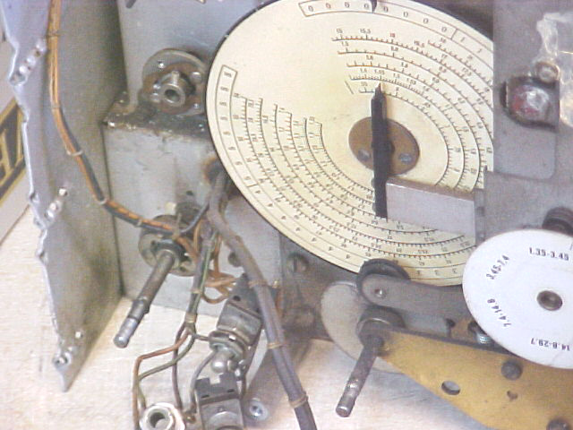
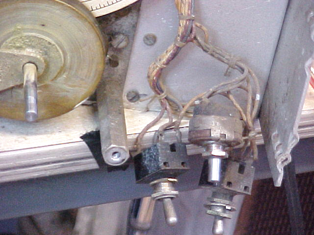
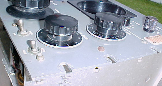
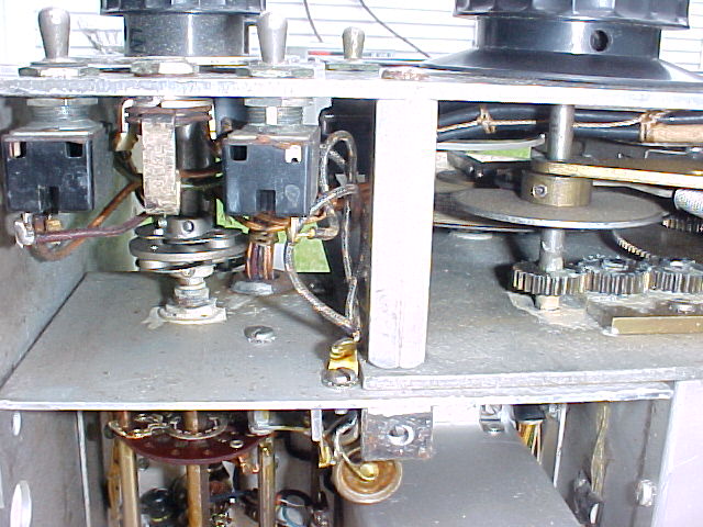
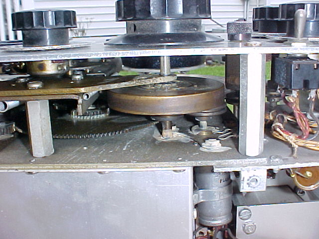
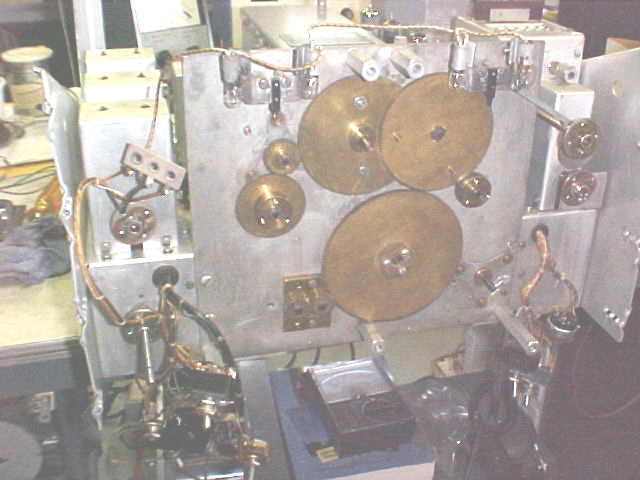
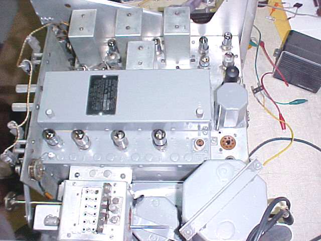
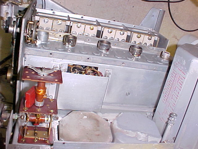
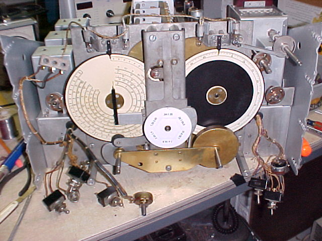
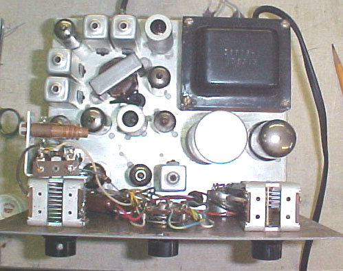
The front area of the chassis is shown after panel removal, no cleaning has been done, grease on shafts is obvious, and dirt very evident on the top of the chassis in the center pic.
Each side panel is missing the 3 screws and threaded backup plate fastening it to the front of the chassis. Bolts, nuts, and washers have been now installed to strengthen this area. Several knobs are missing setscrews, they will be replaced. All shafts will have to be filed smooth, 2 knobs were very difficult to remove. There was an assortment of screws holding the front panel on, proper type and sized stainless steel ones will be installed. One dial window has a short crack extending inward from a mounting screw.
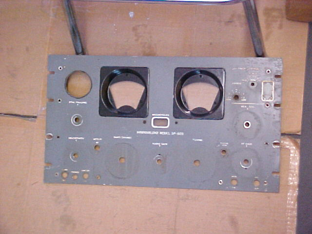
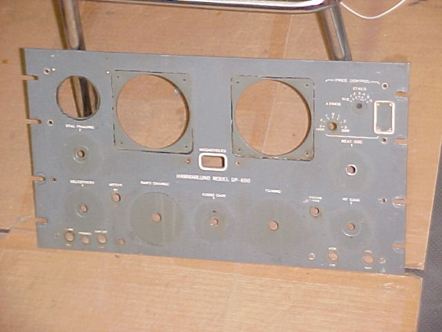
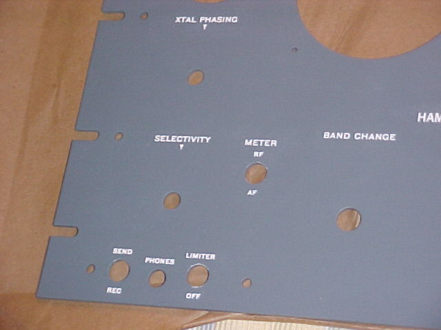
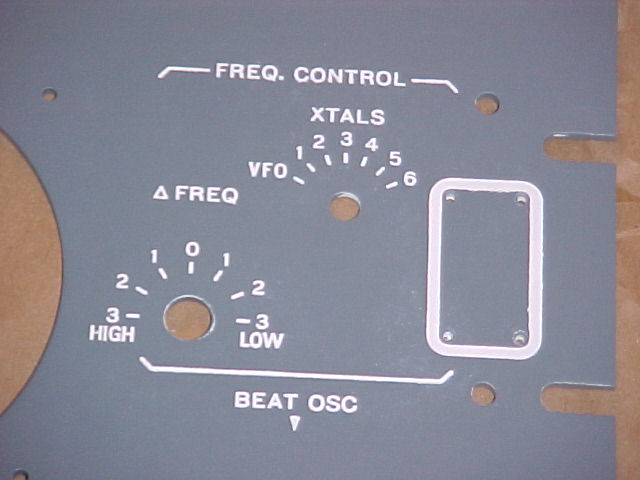
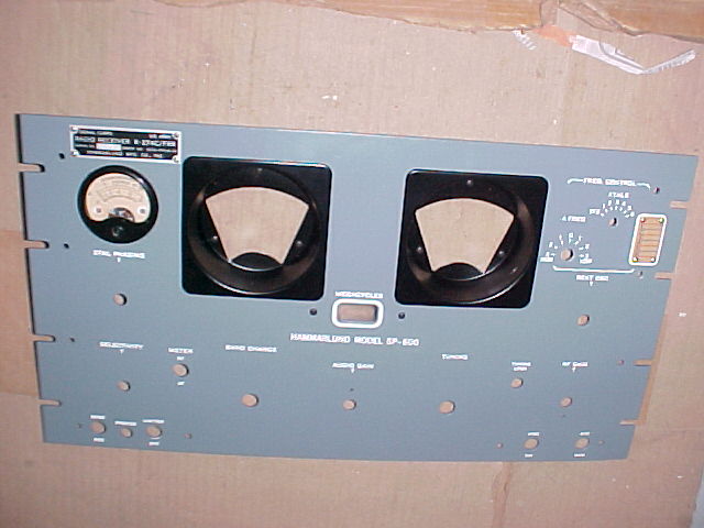
Dirt buildup on the panel is very noticeable after the knobs and bezels are removed. The panel will be stripped and repainted.
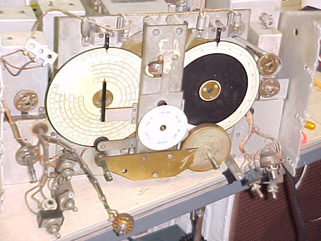
I have removed the dials and some of the band-change mechanism and gearing for cleanup. The chassis has been cleaned, and will get some further spot cleaning as work progresses.
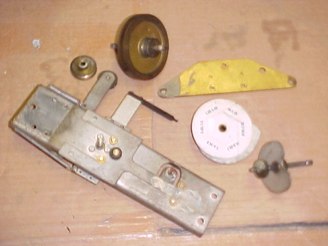
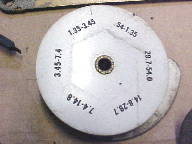
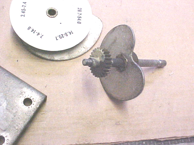
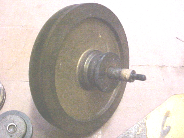
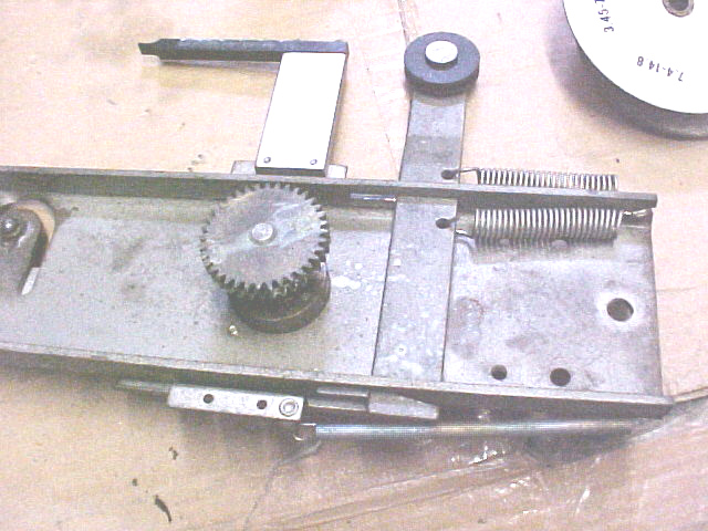
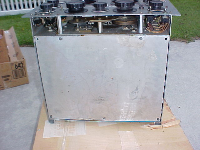
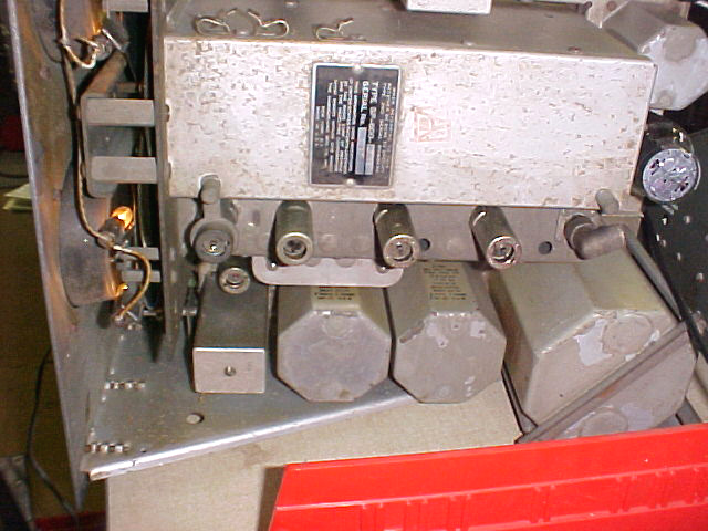
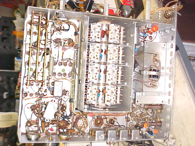
above - parts before cleaning
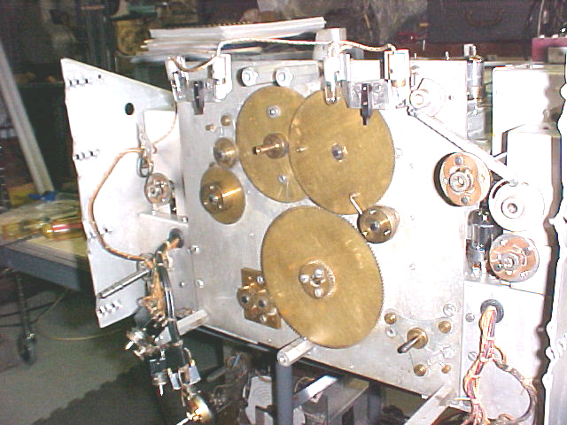
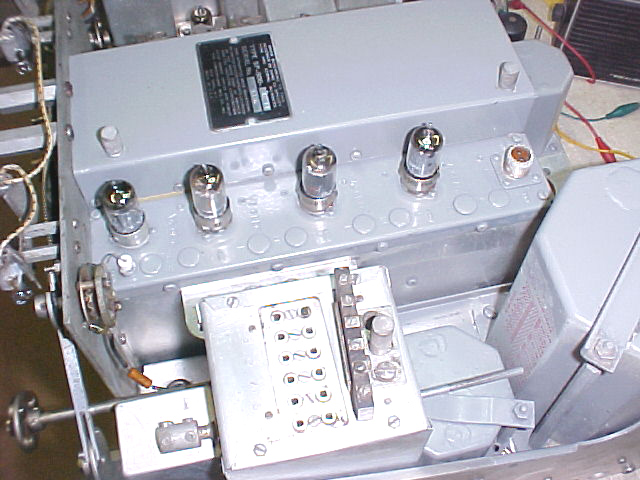
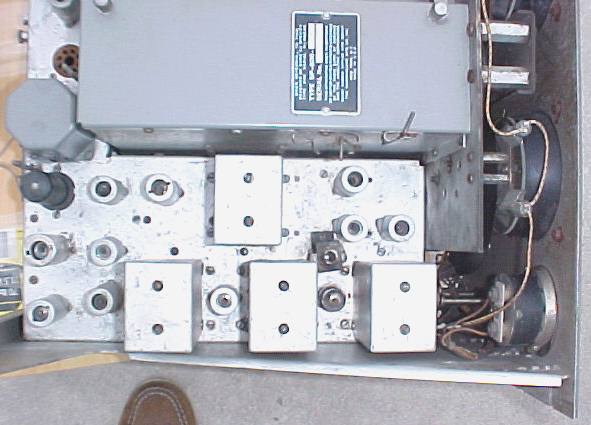
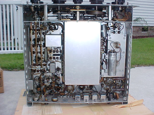
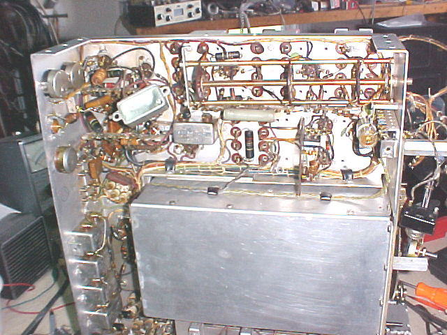
above - chassis after initial cleaning
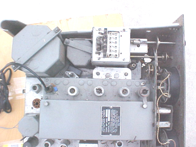
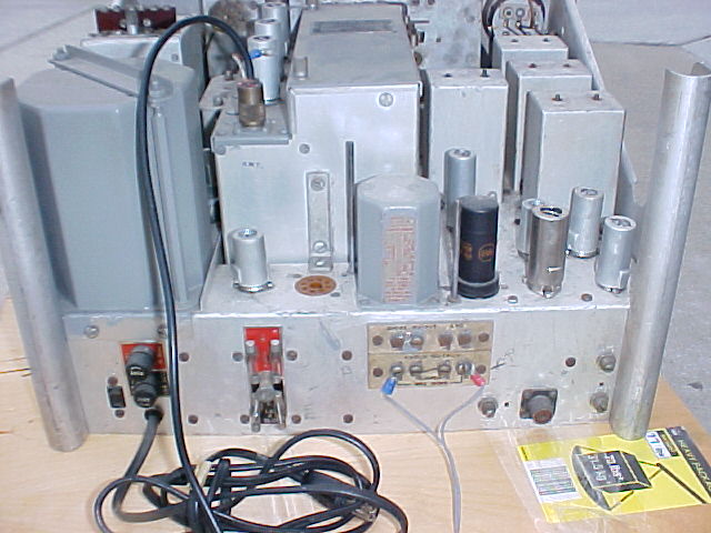
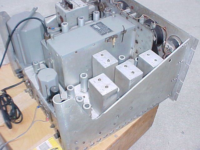
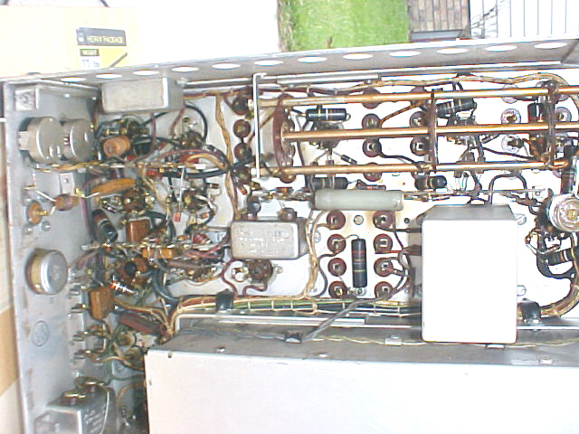
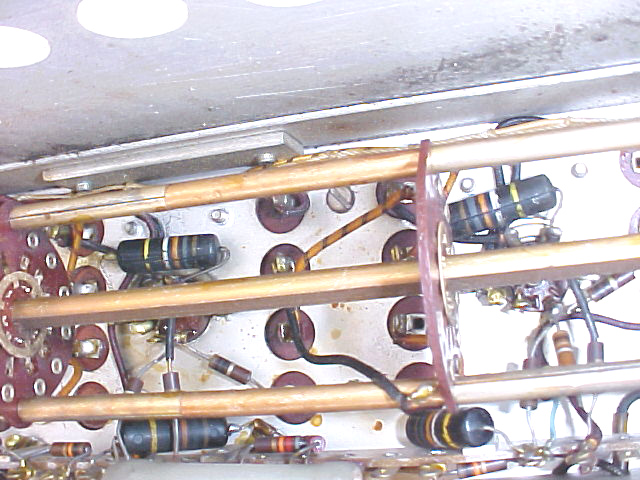
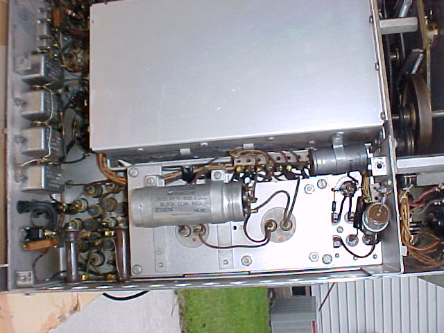
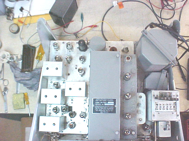
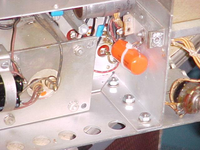
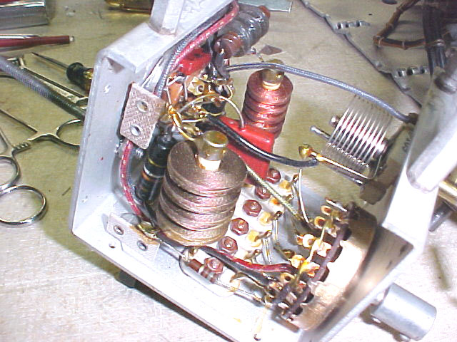
below - back corner after final cleaning, start of re-capping
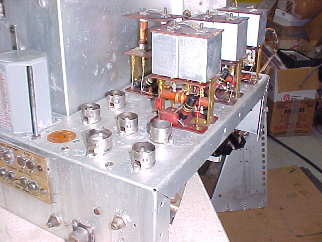
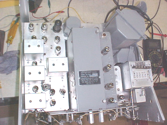
below - this is what the top cover and RF deck could look like after stripping the gray paint.
All under-chassis work has been completed, including turret modules, filter caps, and 3-wire AC line cord w/ AC rated bypasses.
V-14, 2nd det./AVC socket had small SS diodes across pins 1-7 & 2-5 to "replace" the tube - removed, similarly at the HV rectifier, V-19, also removed. C-128, 10mf, on -10v line at V-11 (increases AGC delay w/BFO on) has high ESR, replaced. C-163, .25mf@600v has ~ 500megohm at 600v, it's OK (B+ de-cplg to V-1 & V-2). C-129A&B, .05mf@600v bathtub, both secns >100mohms@500v, OK (IF driver plate & screen de-cplg). Replaced all BBOD's in 6 turret sections. Installed replacements for electrolytic 3-section can, 3 ea. 22mf@4450v. Left side panel and HF osc. cover can cleaned, buffed, re-installed (but not shown in pix).
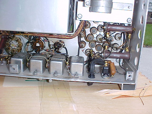
Right hand topside work
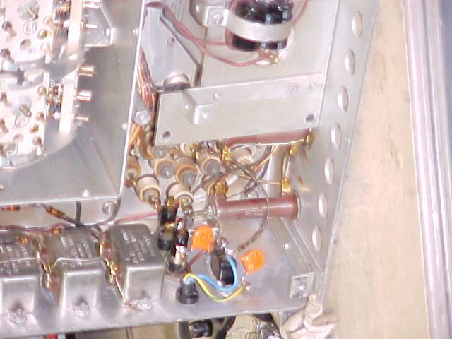
Right side plate has been removed for better access. Filter chokes have been lowered, FCU (xtal unit) has been removed, "pod" has been re-capped (1-BBOD, disc cer. replacement), pod cover and side if tuning unit cleaned. (chokes not cleaned yet.) RF deck mounting screws have been removed.
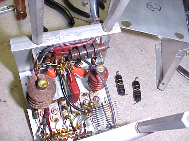
FCU before and after re-capping (2 BBOD's replaced with Orange Drops.) Cover, just visible, has been cleaned, buffed, and re-installed. FCU ready for re-installation, then chokes will be cleaned & bolted in place, leaving the RF deck as the only area with BBOD's to be replaced. Side plate will be cleaned, buffed & re-installed after RF deck is done.
The panel and bezels have been painted and will be here on Fri.
RF deck removed, panel and bezels arrived Thurs. from paint shop. Had started work in RF deck, but did lettering on panel, then finished RF deck Fri.
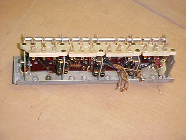
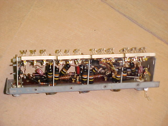 RF deck before starting work - 21 BBOD's in there.
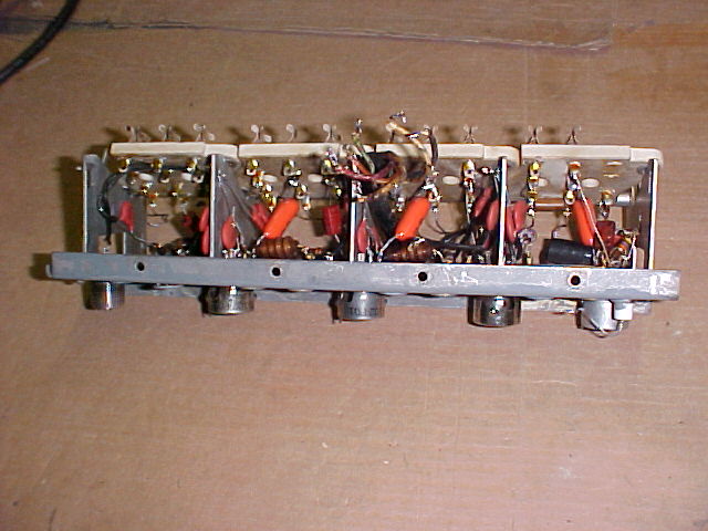
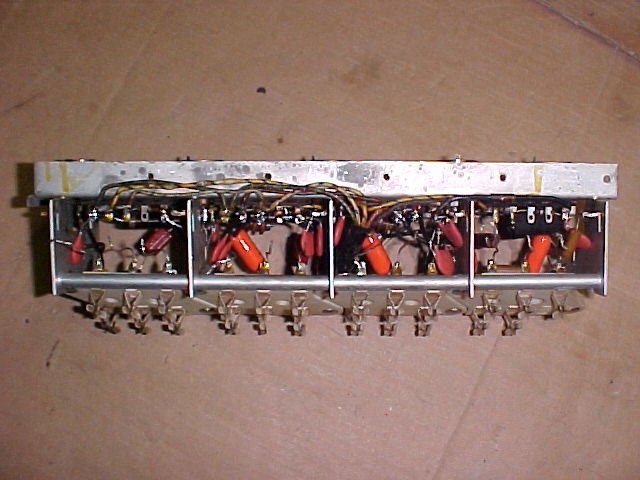 RF deck completed, with new capacitors & ant. connector
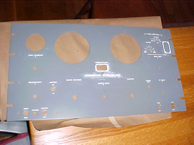
panel in process in first pic, finished in others
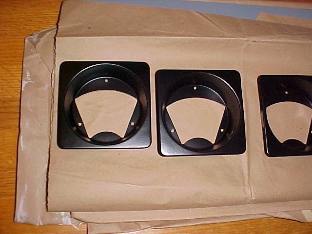 bezels ready to install
Xtal control unit (FCU) has been re-installed, RF deck has had one broken contact for the turret modules replaced (swapped out one that is not used) and reinstalled. IF cans and right side panel cleaned & buffed, side panel re-installed.
Tues. nite
Front mechanisms cleaned & re-installed, panel pieces assembled, ready for installation
Panel installed with new SS hardware, all knobs cleaned & in place. All tubes were checked before installation, 3 6BA6's were replaced. 455kc IF and 3 low bands in RF deck aligned on Wed., completed alignment on Thurs. nite after sailing all day. All screws & misc. hardware were wire brushed with brass brush before re-use, to clean up. All shafts were cleaned and de-burred. Cleaned all pins in turret modules and treated with DeOxit. Installed a 6AC7 in FCU & checked xtal operation.
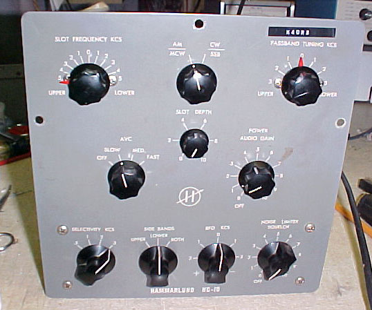
Started on HC-10 ckout & alignment. It seemed to have no AVC generation, turned out to be a bad pin contact in 6BV8 diode section. 455kc was way off, about at 444kc, 60kc IF was close. Put 455 to 454 as is the SP-600, put 60kc right on. Tested all HC-10 tubes. After proper alignment and familiarization, it is working well, no parts required. However, it is necessary to put the "sideband" switch in the opposite position from the actual sideband being received. I think this would happen if the oscillator freq. was on the "wrong" side of the IF freq., but it can't be moved there, it is where it should be. The front panel was cleaned after the picture was taken.
This one is done, I can't think of anything else to do on it.