
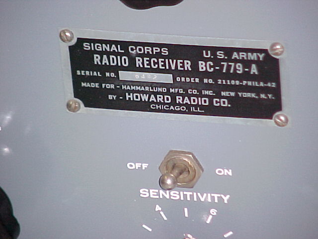
BC-779 - SP-210LX refurbishment
This receiver covers 100-200kc, 200-400kc, 2.5-5mc, 5-10mc and 10-20mc.
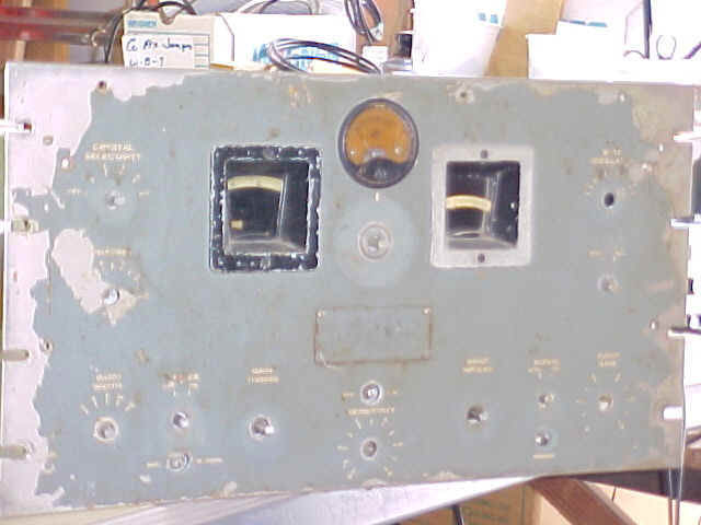
"Before" pix, I didn't take very many, it was very dusty, panel was bad looking, but almost everything was there & original. Only the xtal phasing knob was gone, as the phenolic shaft had broken sometime, as many do. (click on the "thumbnails" for full size pix)
I spent several hours over 2 days. replacing over a dozen
capacitors, and half a dozen resistors. The caps were "leaky",
had developed some resistance, and the resistors had drifted very high in value.
When I started, I just thought I would do the audio stages, as they seemed
worst, and then put power to it & try it out, since the previous owner said
it had been used a year ago or so. But, I went ahead on the rest under the
chassis, as it wasn't too hard. It's easier to work at the tube sockets
for the RF section if the long shaft to the noise limiter switch is removed by
removing the 2 screws holding the switch bracket to the chassis.
There are still some, in the
"tuner" or RF stages, that are very difficult to reach without major
disassembly, I'll get them later. I then powered it up, and it worked well,
on all bands. I hadn't done any alignment, so it should get even better.
I listened some more the next night, and had some good music from foreign broadcast
stations, and 3 long wave aircraft beacons on the low freq. bands. I did
put a properly matched, large, speaker on it, and the music was "hi-fi".
Later I'll spend some more time to clean it up, and remove the front
panel and repaint it & fill the engraved lettering with white acrylic paint.
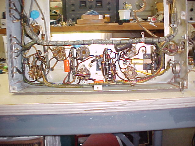
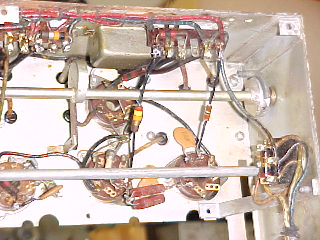
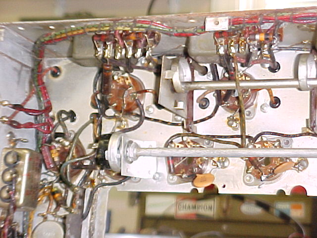
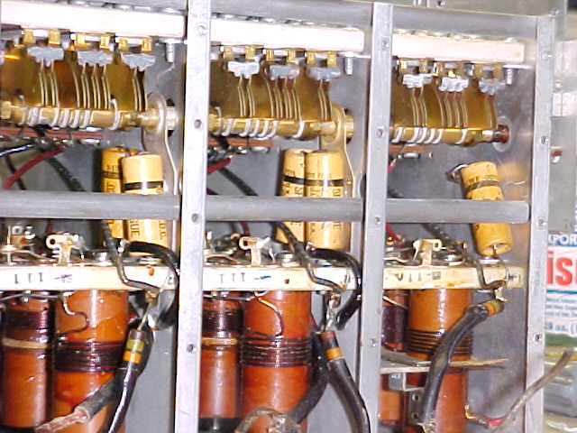
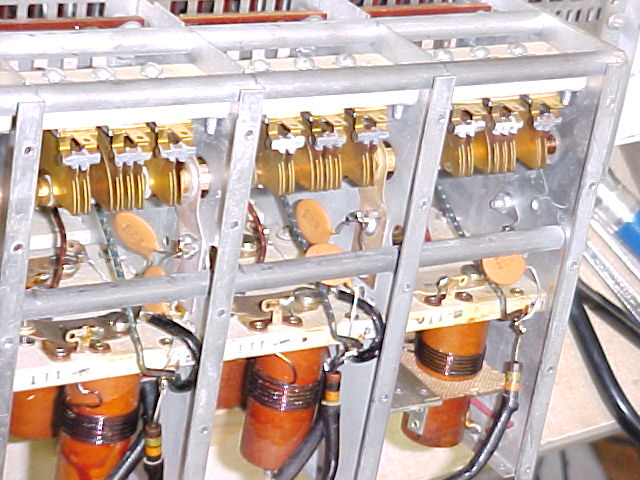
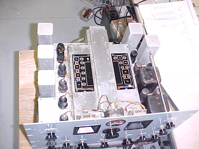
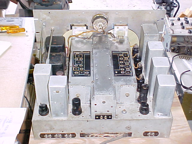
The under-chassis views, showing the replaced components, note the noise limiter shaft & switch.
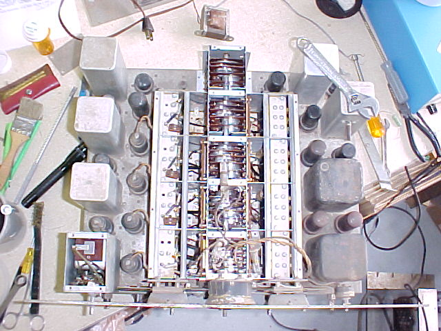
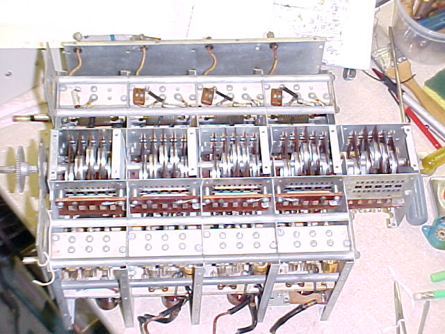
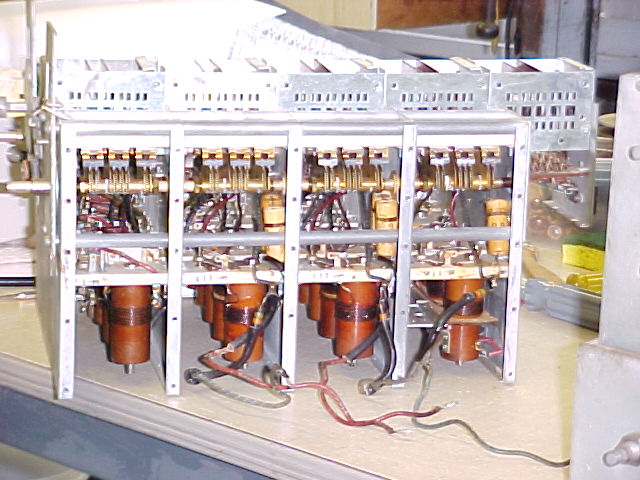
I did pull the tuner, as I knew from the schematic that there were about 5
paper capacitors in there, and resistors, to be checked. I had earlier
checked 20 caps that had been replaced, 15 showed leakage at only 25 volts, all
showed it at 150v, so I knew those in the tuner needed attention.
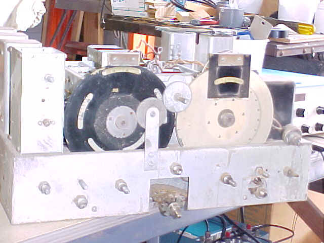
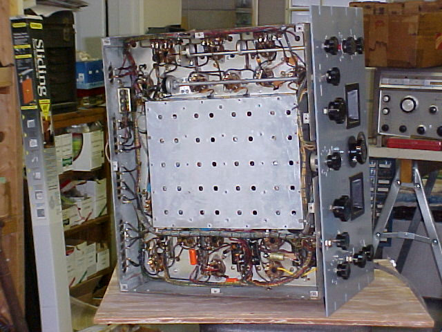
The tuner is not quite as hard to remove as the RF section of the
SP-600 is. Having grid caps for the 4 tubes helps. There are 3 leads
to tube sockets from one side, and 5 leads to a terminal strip on the other,
which must be removed. Then after all the mounting screws are removed, the
tuner will lift out. The front panel must be removed first, and it's
advisable to remove the dial assemblies, particularly if they need cleaning.
The grid coupling caps & resistors at the top of the tuner need
to be checked, I replaced all 3 resistors, the mica caps checked OK (but see
later).
Panel work
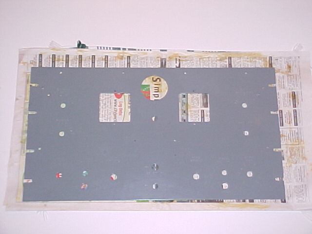
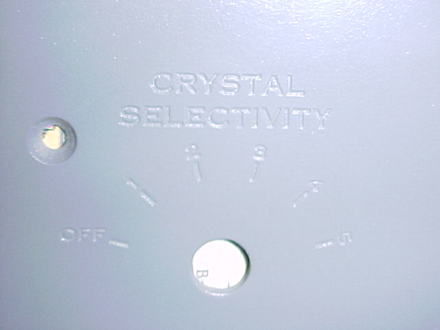
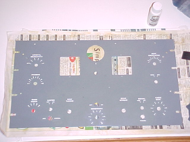
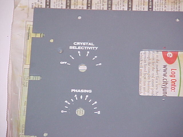
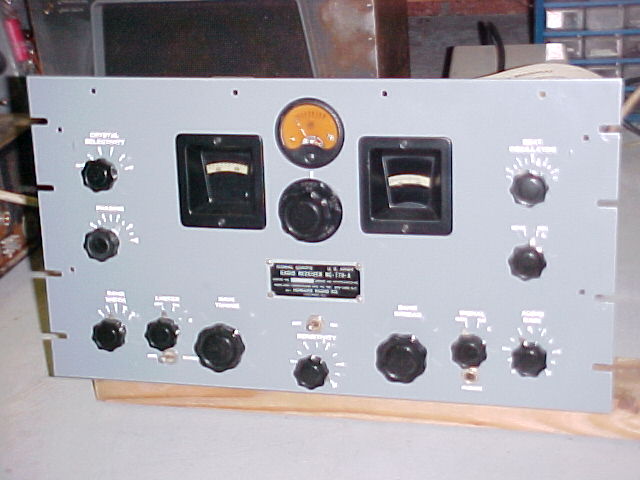
I stripped the remaining panel paint, sanded it with 240 grit paper, primed and painted it. I wet sanded the finish coat with 400 grit paper to remove any orange-peel, and used artist's acrylic paint to fill the engraved lettering. The dial bezels were sanded, primed and painted with Satin Black, as was the S-meter. The knobs were soaked in soapy water, cleaned with a toothbrush & then waxed with paste wax.
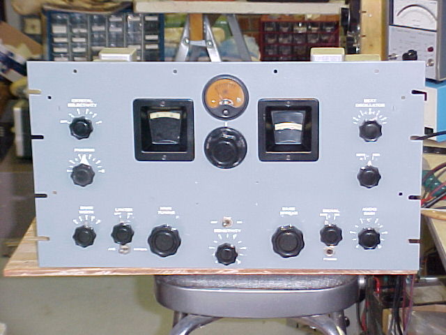
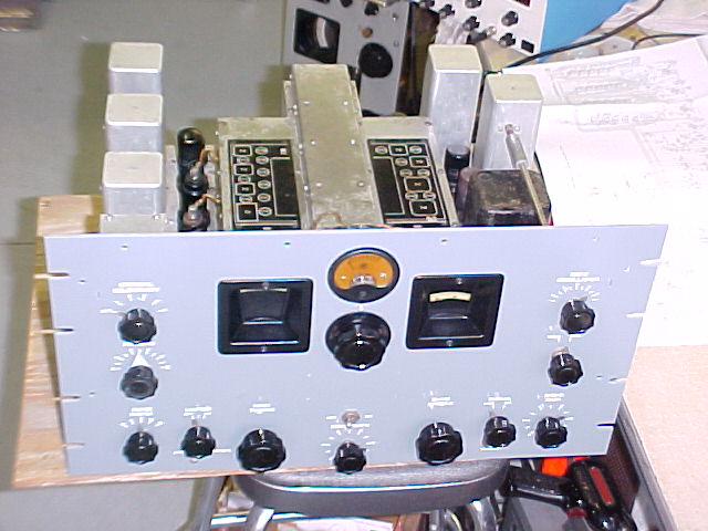
Finished product.
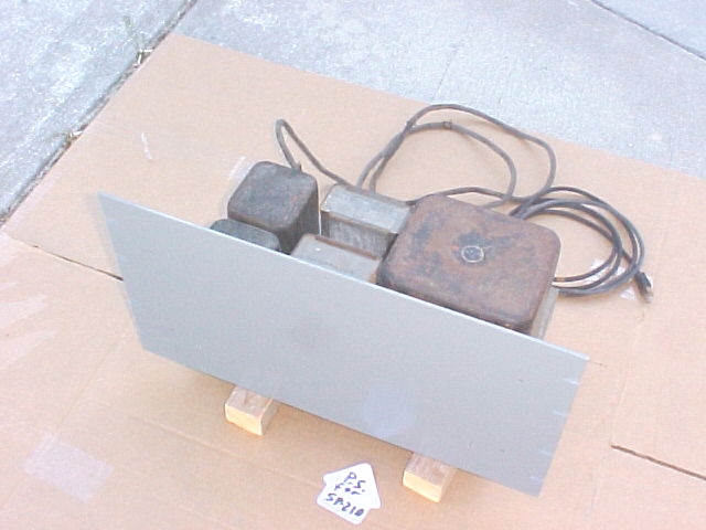
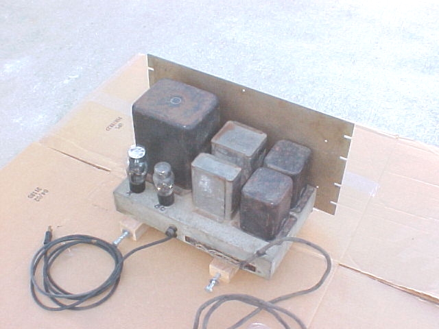
I checked voltages from the power supply, and at tube sockets. The supply should give +140vdc, +270vdc, +385vdc, -50vdc and 6.3vac. The high voltage lines were -50, 110, 240, and 330, & I measured 10, 4, 65, & 42 ma on each. I had already changed the AC line tap on the transformer to the 125 VAC position, and my line voltage was 122, so I expected things to be close, maybe a little on the low side, but not this much, particularly on the 140volt screen supply. The tubes were only seeing about 100v on the screens, after their dropping resistors.
The power supply, at 60 lbs, is not under designed. The screen voltage is supplied from the 270vdc line using a voltage divider/bleeder resistor, which checked out OK when cold, but apparently drifted high when heated under power. It was changed to supply close to 140vdc, and receiver sensitivity seemed to improve.
it's evening, 10/14/02 now, I hope to add some more details in another day or
2.
now it's 10/17, here's a little more:
Earlier this week I realized that it was not very sensitive on the 100-200kc band, really just about deaf. So, I rewound the 100-200 kc antenna coil primary and it was much better there. It had shorted turns, looked like maybe it was "cooked", possibly from nearby lightning sometime. Actually, I went to a local motor shop to ask for some wire & they did it for me. 74 turns of #32 wire, I think they measured the size wrong, as it took up more space than the original, but the turns count was OK.
Since completion, I've enjoyed some bandcruising with this radio. SW broadcast stations come booming in, and good music can be found & enjoyed. I've even copied some more of the VLF non-directional beacons. There's not a lot other than NDB's on the VLF bands, but a lot of people do enjoy VLF DX-ing, and with an appropriate antenna, this should do the job.
Both the receiver ant the power supply have the original bottom covers in place now.
View the original advertisement for
this series
(in Adobe Acrobat format)
Al, W8UT