
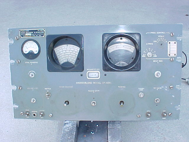
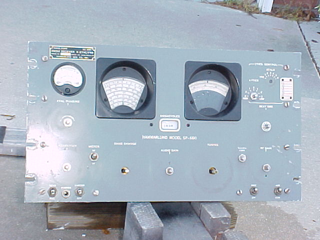
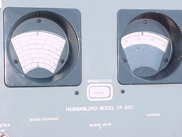
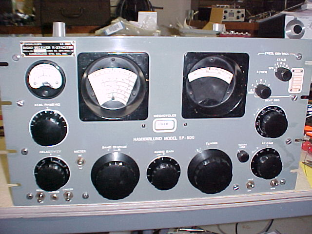
SP-600-JX-14, s/n 8655
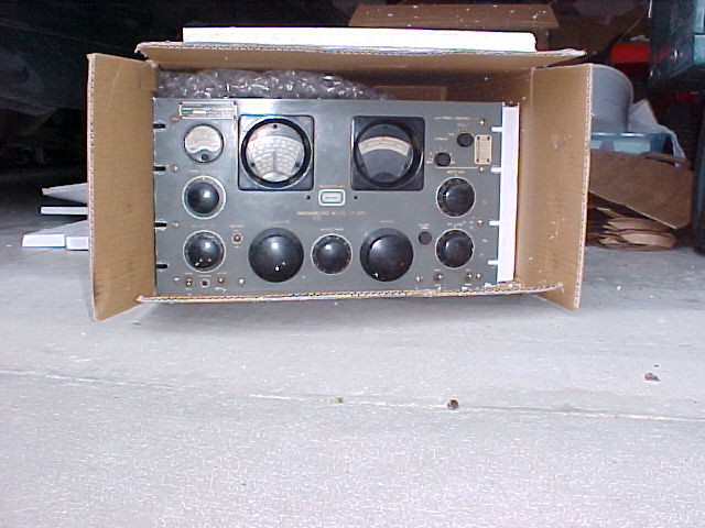
Arrived 4/2/04 pix taken then, during unpack/inspection.
Initial valuation/observations:
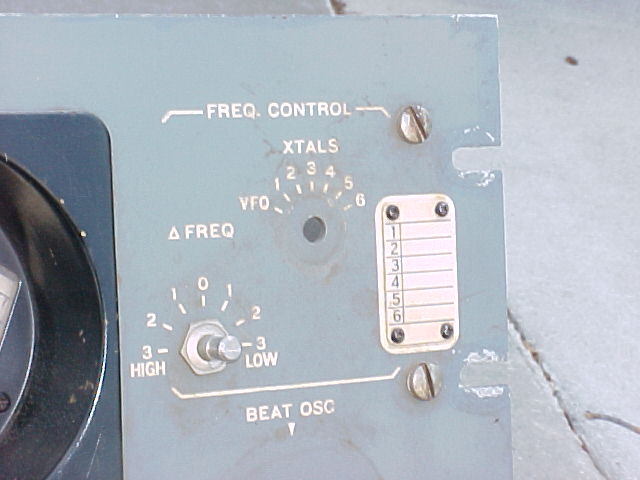
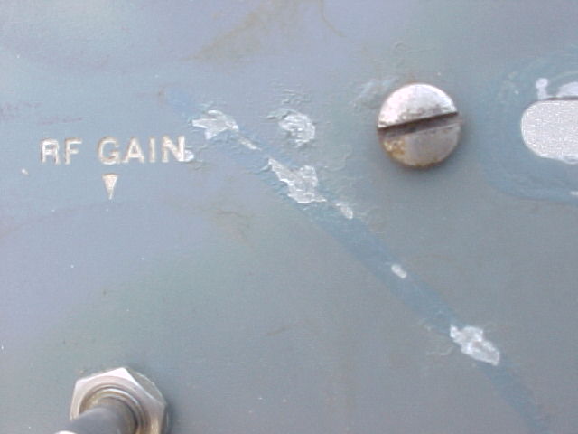
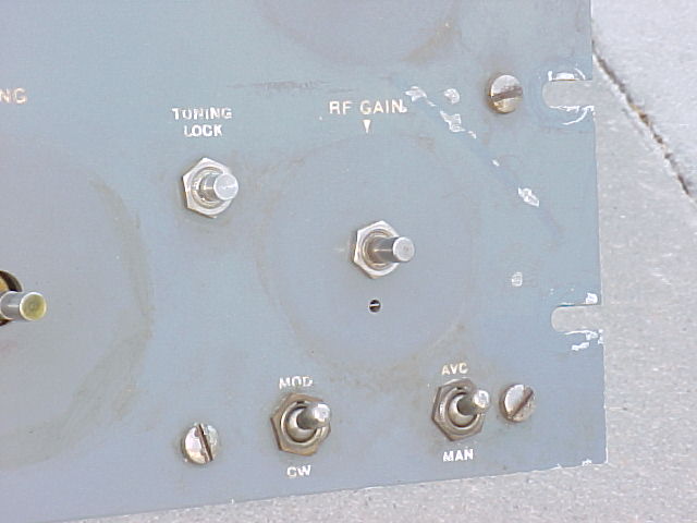
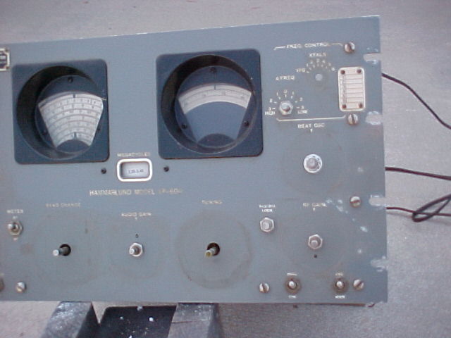
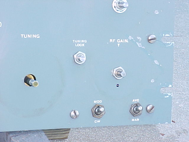
Relatively clean, dust had been blown out before shipment, it's "grimy" and will benefit from cleaning. Aluminum hassis shows no corrosion, RF deck (steel) is cleaner than most that have not been MFP'd. All tube shields in place, incl. hold-downs on 6V6, 6AC7 (FCU) and 5R4, which is the large ceramic base type. Has metal cover for extra fuses. All hole plugs in place on RF deck, no xtals in FCU, xtal hold-downs all intact. All dial lamps in place (and working), all knobs and switches are original. Front panel is in fair condition, usual chips/scrapes at rack mounting slots, some scrapes/chips near RF gain knob.
Filter capacitor may be a replacement, of the original type, terminals show signs of wire re-soldering. It has a note on a tag re: B+ to FCU disconnected. After a short power on time at 90vac input, then discharging, the ESR checked at 1.3, 1.3, 1.4, very good. Will need to decide whether to install new discrete electrolytics.
It has all BBOD's,.no cracked ones noticed. AC input is on the 117v tap (#4, will move to #5, 130v, to reduce "general stress" due to the AC voltages of ~125 common in most areas. Has 2-wire power cord, will be changed to 3-wire.
Pins on turret modules are quite clean, and show very little wear. (BBOD's in the modules.)
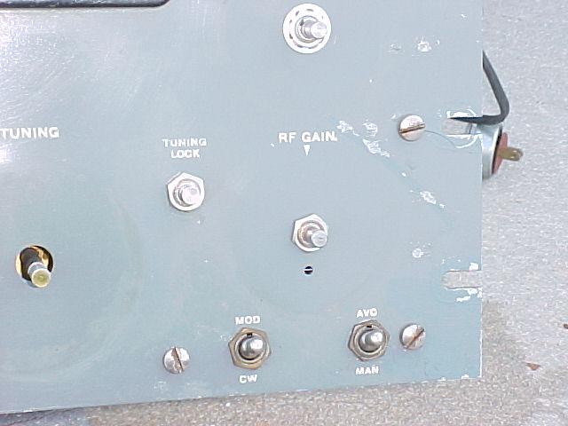
Powered up, it seems very sensitive, high S-meter readings partly due to setting of mtr adj. 15mc WWV is at +80db, and is less than a pointer's width off freq. 3/8/16kc selectivity posn's vary widely in stage gain. All 3 front panel toggle switches, AVC/MAN, LIM, Send/RCV, & MTR, are intermittent. Some DeOxit may fix, hopefully. Did notice a few places under the chassis that appear to have had some soldering done, will ck for any mods or replaced components while doing the re-capping.
--------------------
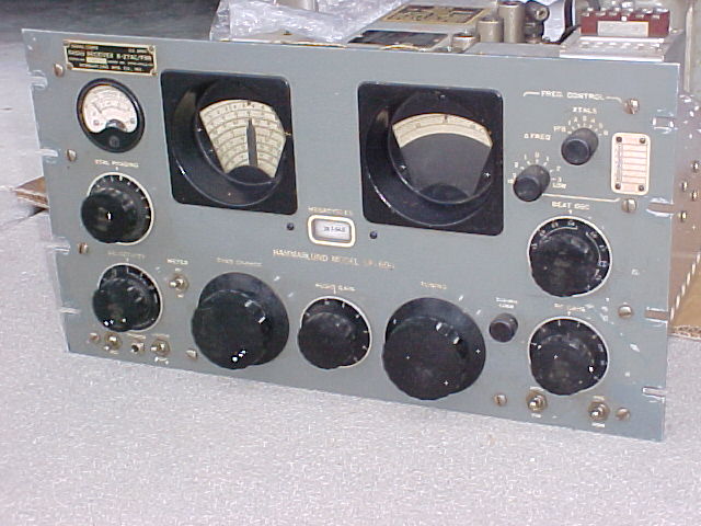
before cleaning
----------------------
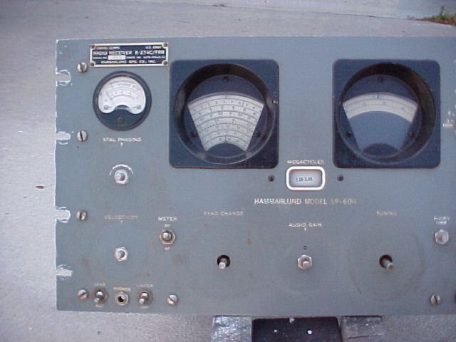
after first step cleaning
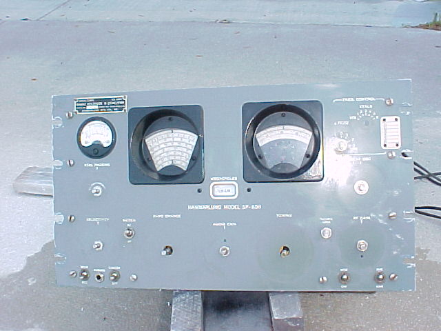
Differences in color are mostly due to different ambient light. Difference in grunge is due to cleaning. Chassis is much brighter, most of the nicotine & finger oil staining is gone from around the knobs. Application of paste wax will remove a little more, but when knobs are back on the skirts will cover most of the remainder. Tube shields have been cleaned, knobs are presently soaking & will be cleaned before reinstallation. Lettering has brightened up. Dials are cleaner.
-------------------
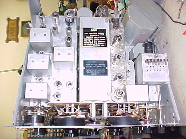
Waxed knobs. Applied DeOxit to all tube pins as they were re-installed, fix 2 knobs/shafts that were burred. Installed new 0A2 & 6C4 tubes. Check out operation before starting disassembly. Remove rt. side panel, lowered choke assy, removed FCU, opened T-2 "pod," remove connections to RF deck & removed deck.
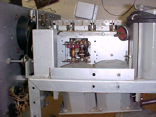
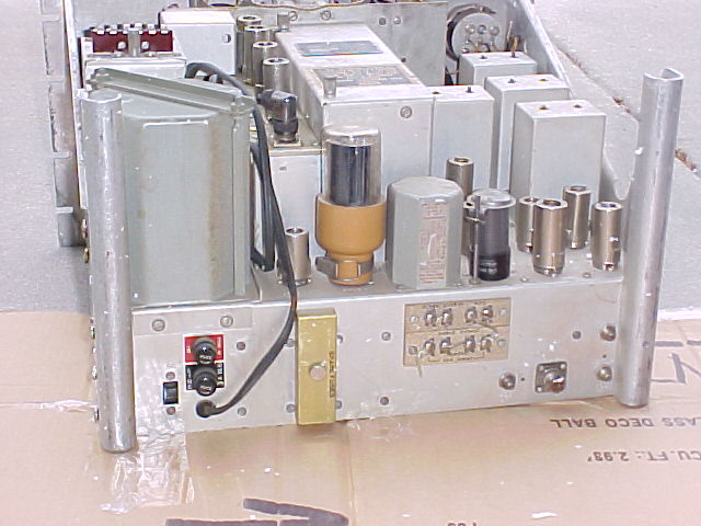
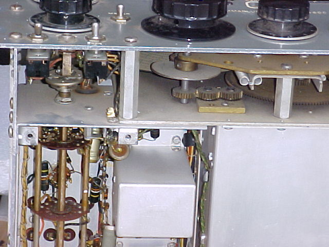
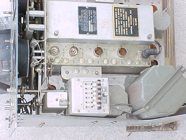
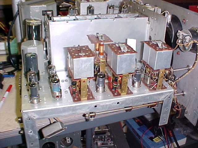
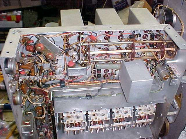
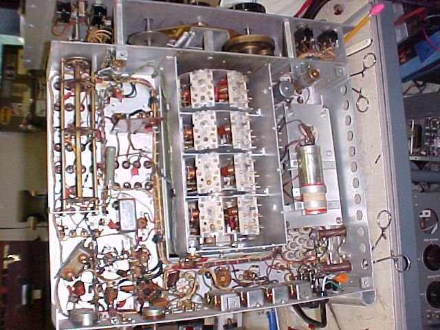
RF Deck
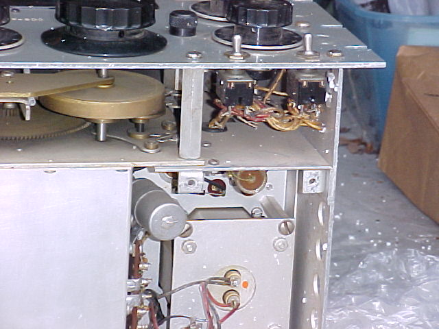
T-2 "pod"
side plate & pod
Pod closeup
9 wires to remove
cover removed,
to
remove RF deck
chokes have been lowered
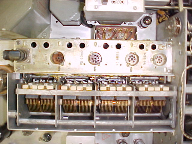
RF
Deck rear
RF Deck front
showing
most of the 15 wires to be unsoldered
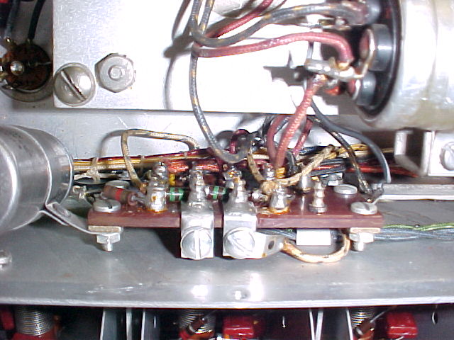
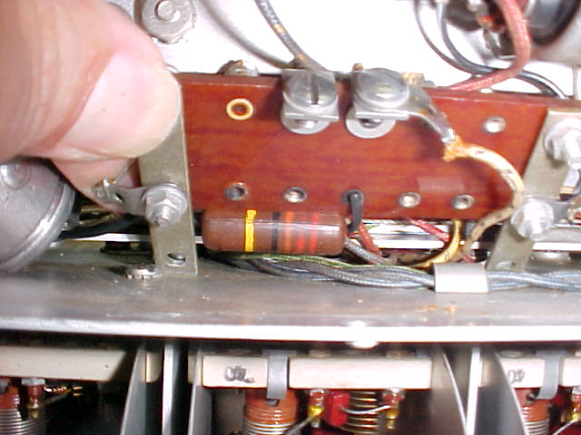
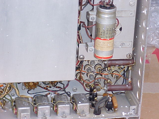
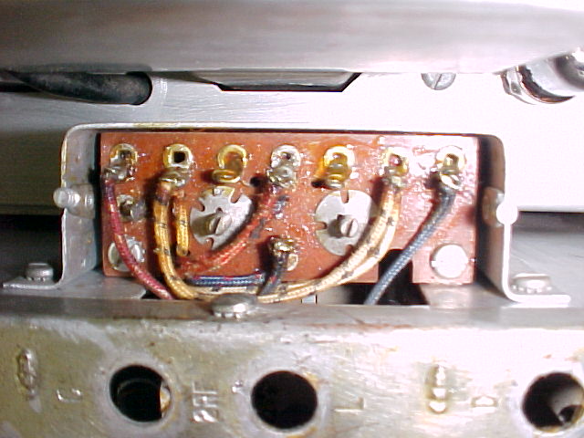
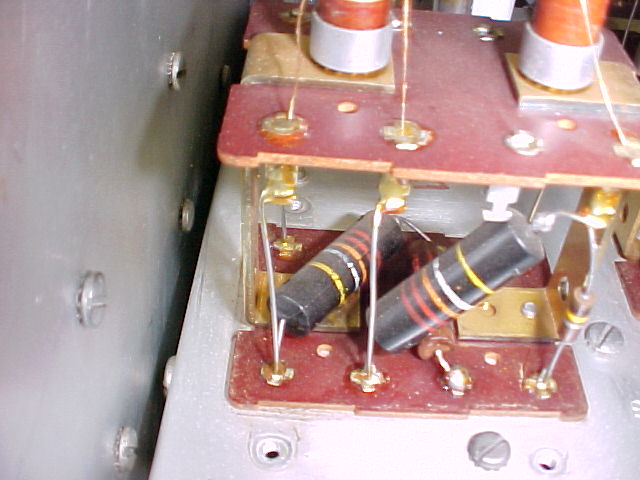
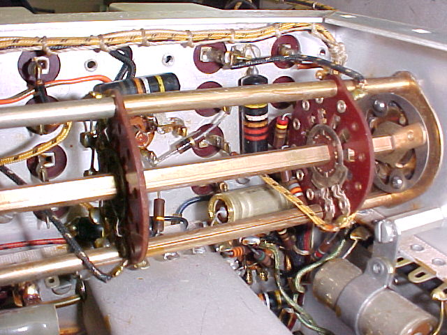
E-16
term board
E-16
hidden
BBOD (brown)
several wires to FCU to be unsoldered
--------------------
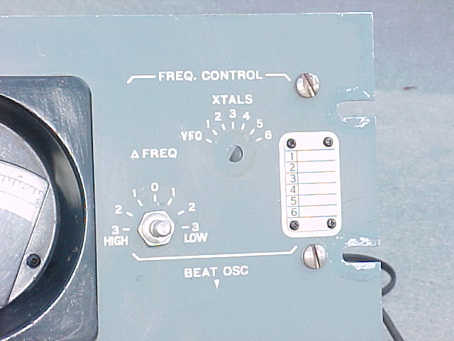
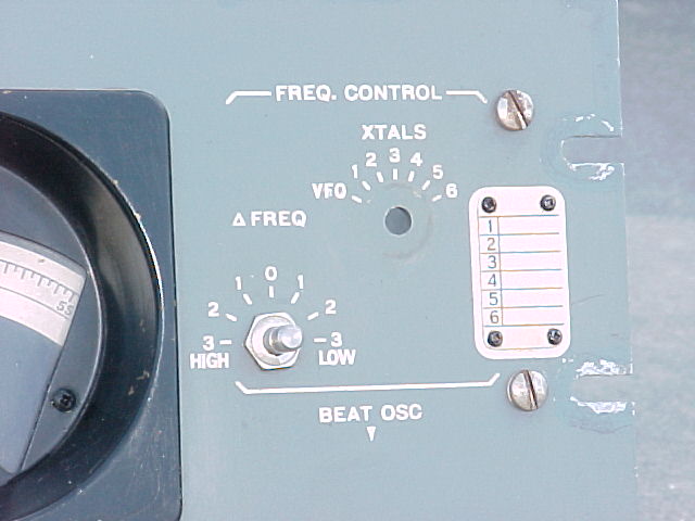
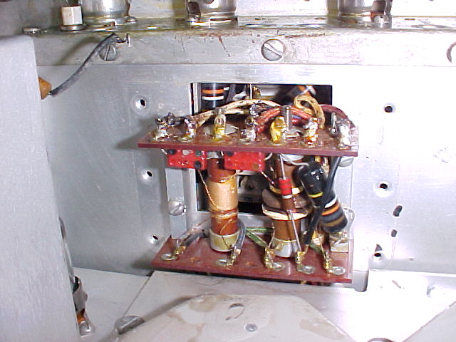
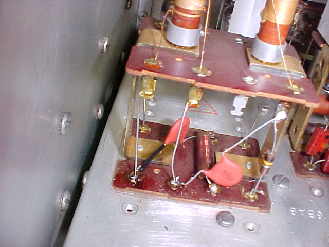
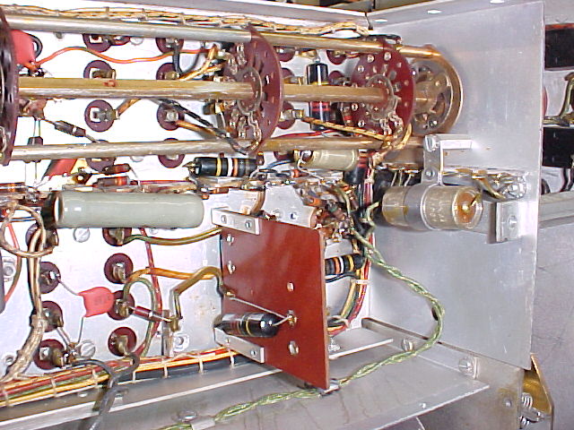
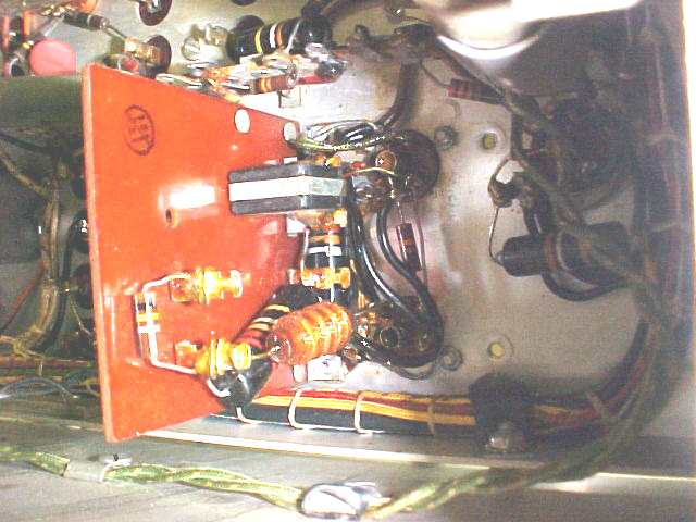
Frequency Control Unit (FCU)
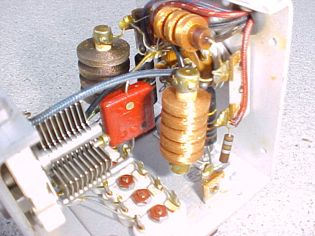
cover
removed, one BBOD behind each vertical RF choke
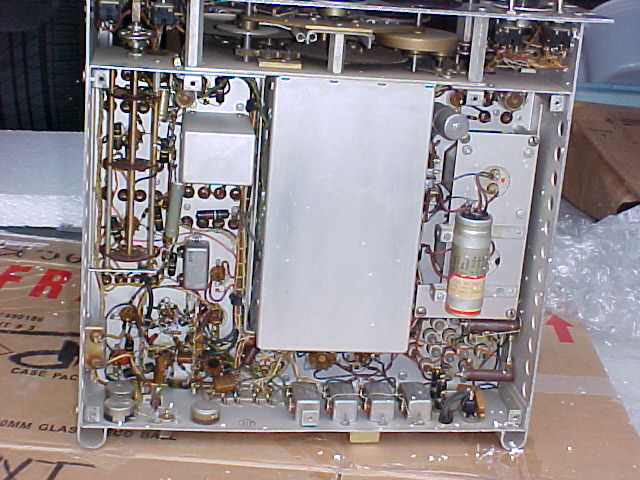
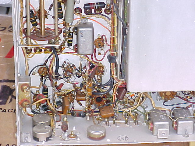
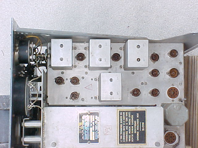
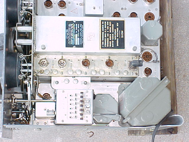
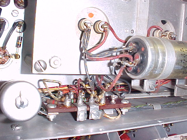
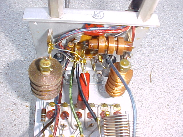
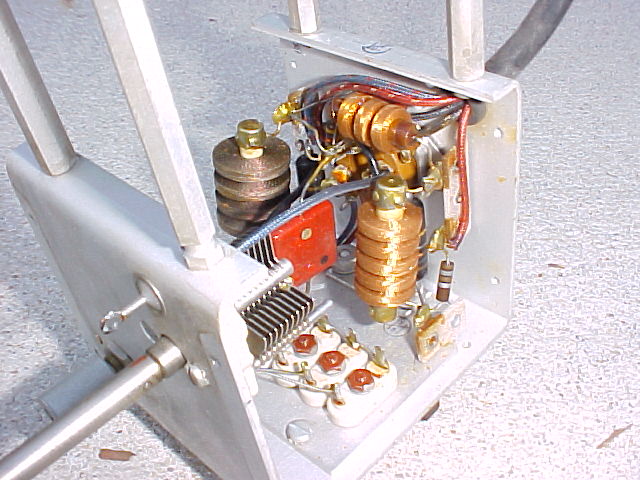
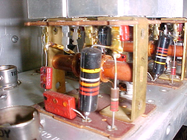
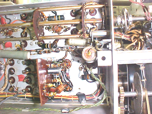
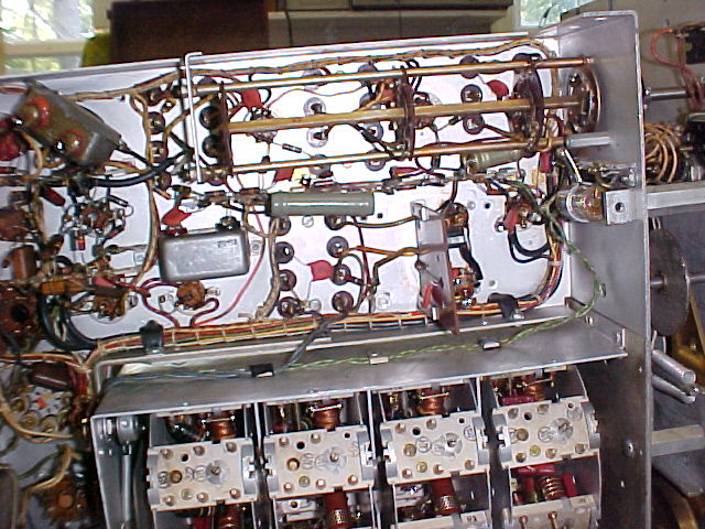
RF Deck before re-capping

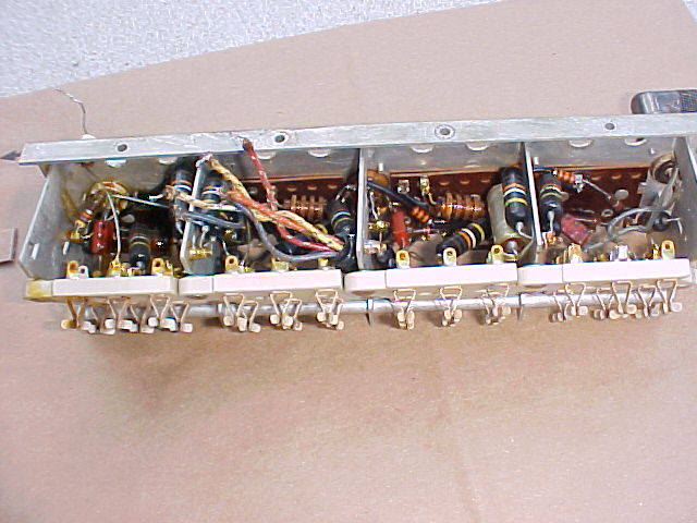
note split BBOD's in closeups
---------------------
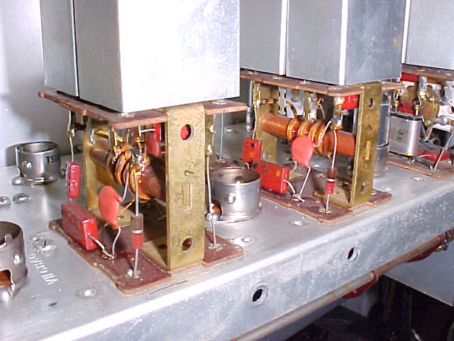
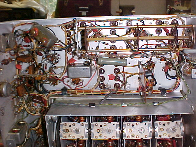
RF Deck after re-capping
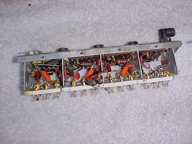
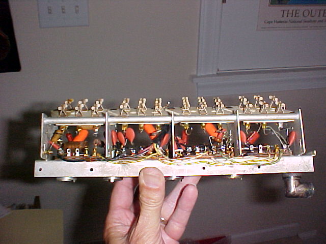
20 BBOD's were removed, 17 bypass and decoupling caps replaced with disk ceramics, 3 coupling caps replaced with Orange Drops. Of the 20, about 10 had at least 3 megohms resistance at 400vdc (fairly good), 5 were split, 5 not split. Of the latter 10, some were well under 1 megohm at 300vdc (not very good). None would have provided more than 1 ma. leakage current flow, so in all, not too bad. One 1k decoupling resistor checked about 30% high and was replaced. It was in series with a much larger one (13k as I remember), and the higher value wouldn't have made any difference in operation.
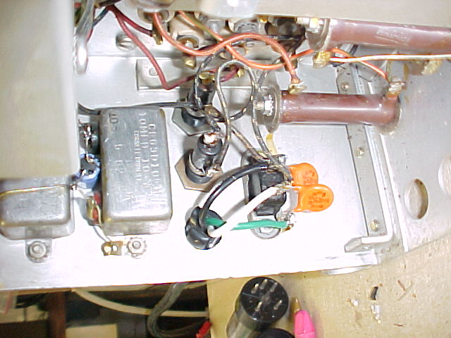
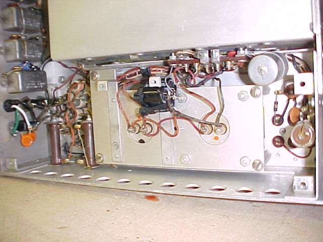
The RF deck and FCU have been re-installed. All tubes were checked, one 6BA6 was replaced. All resistances were checked vs the manual charts. Several were marked for further check, all in HV lines and the charging up of filter caps made resistance checking difficult. The filter choke assy was bolted back up in place, a 3-wire AC cord installed, with new AC rated bypass caps, and the right side chassis plate was re-installed,. The 2 original mica AC bypass caps checked very good at 400vdc after removal. It was noted that a 6 amp fuse was in place, and the label had been changed to read 3 amps. The original spec was for 3/4 amp slo-blow. Actual draw will be checked after all recapping is complete. Primary tap on pwr xfmr changed from #4 to #5, 130v. The right hand side is now complete. It was noted that a "new" wire had been added from between the 2 HV bleeder resistors to the screens of the 1st and 2nd IF amps. No evidence was found of the original wire, which should have been in the laced wiring.
It will be powered up for a check before continuing. The 6 turret modules that have BBOD's will be done next, then on to the remaining work.
----------------------
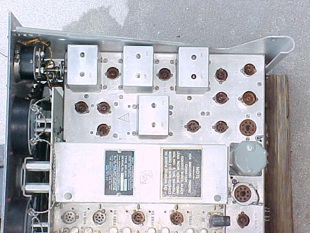
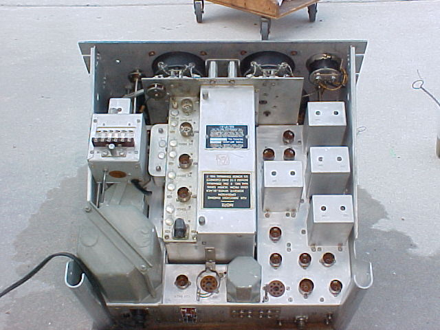
Powered up ck is OK, went on to top-side IF cans, after removing left side panel.
 "before" shots
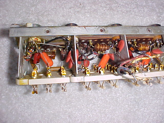
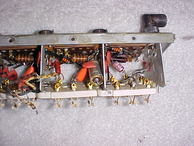
 "after" shots
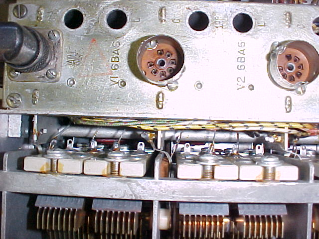
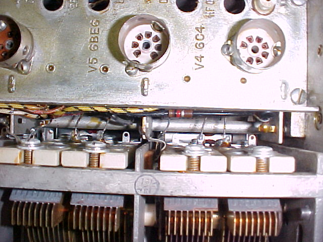
------------------
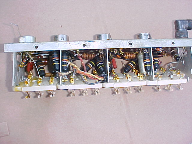
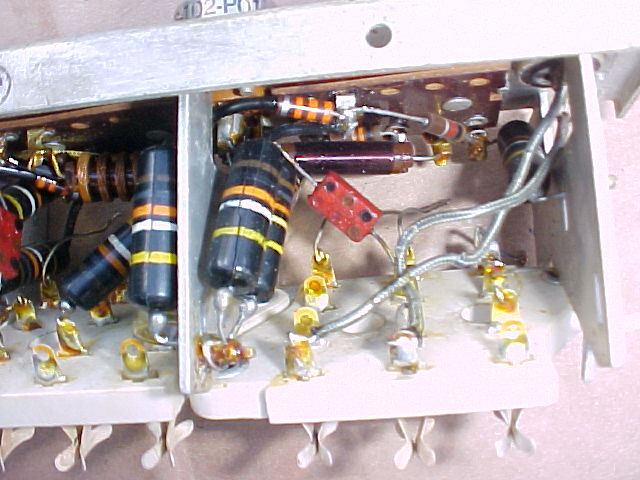
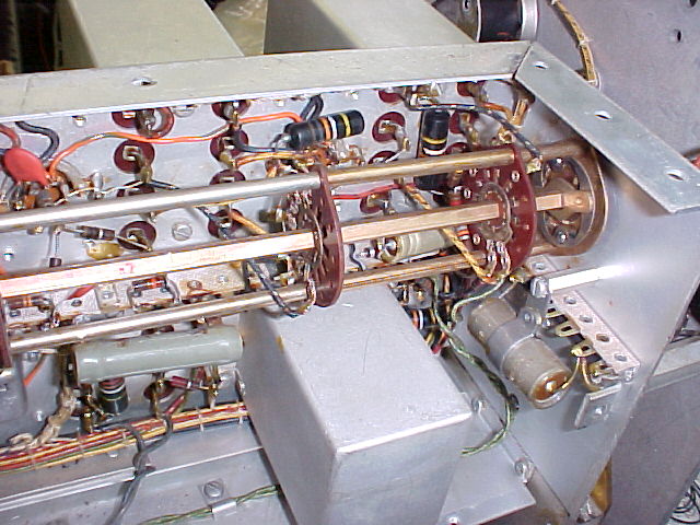
a few shots of the IF and selectivity switch area under the chassis, and showing how tight it can be under there, and how much easier it is with the side panel removed. Some of the (easier) BBOD's were replaced before pix were taken.
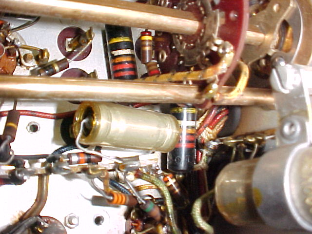
2nd
osc, w/can removed
Things look a little clearer after all BBOD's have been replaced, 21 in these last 2 areas
Of the 21, 7 checked OK/fair, with about 10+megohms resistance at 400vdc, 10 checked to have less than 2megohms resistance at about 300 volts, 4 were visibly split. One of the split ones checked open, one close to a short, 2 with less than 1megohm res.
The only recapping left is the 6 turret modules that have BBOD's, and replacement of the electrolytic filter caps.
That's all for this week. Hamfest Sat., holiday weekend.
------------------
In the first 2 weeks of June, the turret modules have been recapped, and almost all re-assembly has been completed. There were 6 BBOB's in these modules, none was better than about 5 megohms. A new capacitor tests 100+ megohms. I know have 50 capacitors that have been removed/replaced, it would be fair to say that none of them was "good" enough to keep, about half were definitely causing diminished performance, or undue stress on the power supply components.
Alignment of the IF's and RF sections has been done after letting the receiver "cook" for several hours on several days. The end is in sight.
-------------------
Replaced 2 10mf "bathtub" caps with electrolytics, C-151, the first filter in the bias supply, and C158, the cathode bypass for the 6V6 audio output. Audio sounds much better now. Several toggle switches on the front panel were intermittent, DeOxit took care of that. Stagger tuned the IF transformers, input windings to 453.3, output windings to 454.7, vs 453.8 xtal freq. Audio sounds better. Wider spacing gave "twin peaks" response. FCU checks out OK for use with accessory xtals for fixed freq. reception. BFO was weak, it's output buffer tube was very weak. Put new 6BA6/5749 with best test Gm in 1st RF stage, put that one in the buffer. Worked at matching panel paint to fill in the corroded areas, ended up a little light in shade, but looks better than the bare spots. Will let dry and then put some wax on it to see how it comes out. Made "logging" chart of frequencies on the logging dial.
With the exception of the 3 power supply filter caps, this one's about done. Caps are on order, should come in this week. Had bought some at a hamfest a few wks ago, but can't find them now. Very frustrating.
LOGGING CHARTS
| Frequency |
Log setting |
Frequency | Log setting | Frequency |
Log setting |
||
| 7.500 | 021 | 15.000 | 019.8 | 30.000 | 096.8 | ||
| 8.000 | 064.5 | 15.500 | 040.4 | 32.000 | 138.8 | ||
| 9.000 | 149.5 | 17.000 | 103.0 | 34.000 | 181.0 | ||
| 10.000 | 232.5 | 18.500 | 164.2 | 36.000 | 222.6 | ||
| 11.000 | 312.6 | 20.000 | 225.0 | 38.000 | 264.8 | ||
| 12.000 | 389.2 | 21.500 | 285.5 | 40.000 | 305.9 | ||
| 13.000 | 461.0 | 22.000 | 305.0 | 43.000 | 366.2 | ||
| 14.000 | 530.1 | 23.500 | 262.2 | 48.000 | 464.0 | ||
| 14.300 | 550.8 | 25.000 | 418.5 | 50.000 | 502.6 | ||
| 14.500 | 565.0 | 27.000 | 490.0 | 52.000 | 540.6 | ||
| 28.000 | 525.2 | 54.000 | 581.0 | ||||
| 28.500 | 542.7 | ||||||
| 29.500 | 579.0 |
| Frequency |
Log setting |
Frequency | Log setting | Frequency |
Log setting |
||
| 0.600 | 074.7 | 1.400 | 031.4 | 3.600 | 041.3 | ||
| 0.700 | 163.9 | 1.500 | 069.5 | 4.000 | 109.5 | ||
| 0.800 | 244.1 | 1.600 | 105.9 | 4.500 | 189.5 | ||
| 0.900 | 316.8 | 1.800 | 173.8 | 5.000 | 265.0 | ||
| 1.000 | 383.5 | 2.000 | 236.6 | 5.700 | 363.7 | ||
| 1.100 | 444.2 | 2.200 | 295.2 | 6.500 | 469.0 | ||
| 1.200 | 501.6 | 2.400 | 348.2 | 6.800 | 507.3 | ||
| 1.300 | 555.2 | 2.600 | 399.0 | 7.000 | 531.7 | ||
| 2.800 | 444.6 | 7.200 | 556.6 | ||||
| 3.100 | 509.5 | 7.300 | 569.4 | ||||
| 3.400 | 569.0 | 7.400 | 582.5 |
------------------
6/22/04 I'm done - electrolytic filter capacitors on the power supply section, originally 3 in one can, have been replaced with 3 discrete units. IF alignment was redone while monitoring the waveshape of the 453.8kc IF signal, modulated at 400cps. Alignment was done to minimize distortion of the 400cy audio signal, and to equalize the S-meter/AVC response of the 3 selectivity positions. An additional 33pf coupling capacitor was added to the 51pf original in line to the AVC amplifier to increase the AVC voltage and eliminate overload distortion of the audio on strong signals.
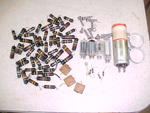 the parts that were replaced. 52 paper "BBOD" capacitors, and as
I said before, it
would be fair to say that none of them was "good" enough to keep,
about half were definitely causing diminished performance, or undue stress on
the power supply components. Half a dozen or more were split open,
some essentially shorted, some open.
the parts that were replaced. 52 paper "BBOD" capacitors, and as
I said before, it
would be fair to say that none of them was "good" enough to keep,
about half were definitely causing diminished performance, or undue stress on
the power supply components. Half a dozen or more were split open,
some essentially shorted, some open.