ELECTROLYTIC FILTER CAPACITOR REBUILD
The basic procedure is detailed in the Drake section, with specific details in each of the others.
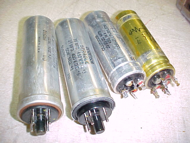
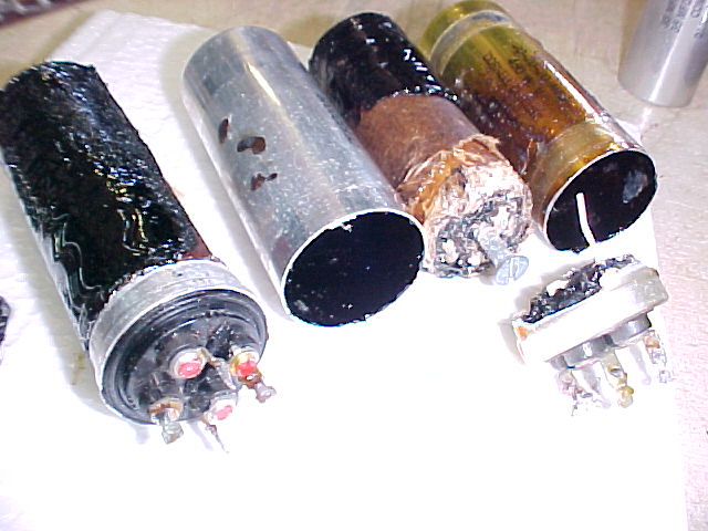
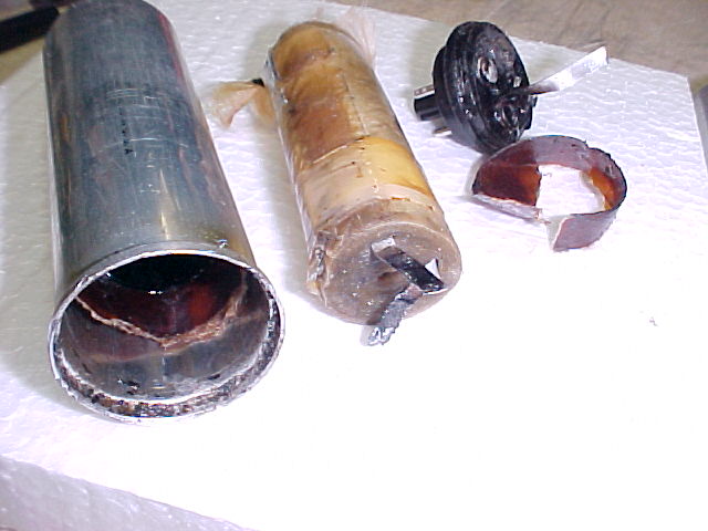
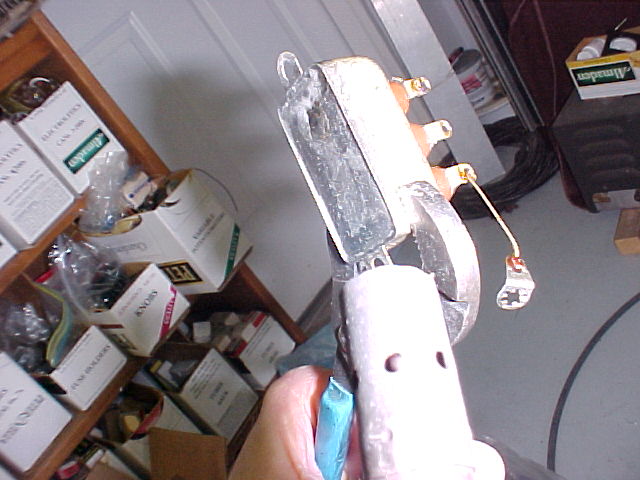
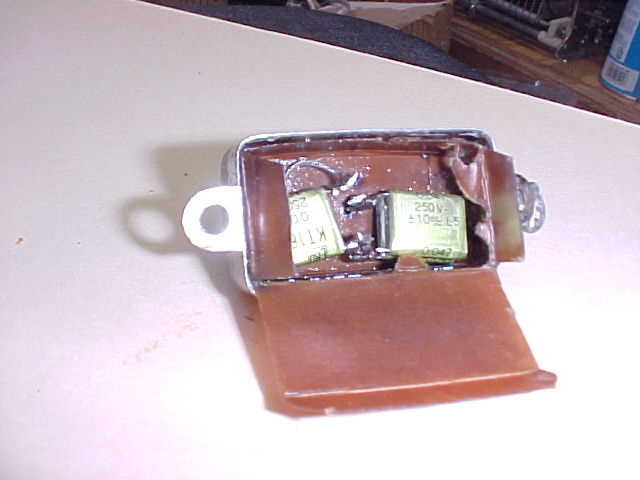
two R-388 filters on the left, 2 SP-600's center, 2x 0.1 bathtub on the right
(click on pic to see full size)
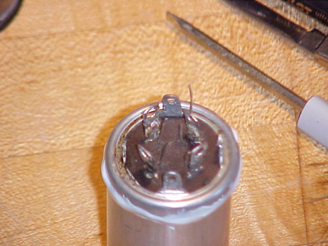
Some pix of the electrolytic cap rebuild for Drake R-4A & R-4B filters.
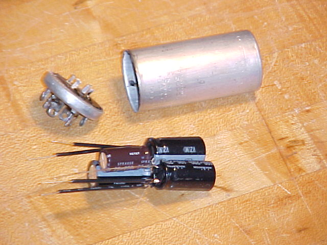
I cut 4 cans of the proper size (1-3/8 x 3inch) apart as shown. I used a lathe, it can be done with a razor saw or even a tubing cutter. The insides came right out of one of them. I had to use some heat from a propane torch to slightly soften the inside material (ukumpucky is the term often used). They all came out in one cylindrical "lump," not as a messy goo. The aluminum leads to each section are easily cut to leave the cap with terminals, and the remains disposed of. The cans should be cleaned inside, there's a little residue on the sides. I used kerosene.
The can had 3 sections of 100mf @ 250volts, and 1 section of 22mf @ 250v. Actual voltage in the receivers is below 200v. I used 200v units for the 100's because the supplier was out of stock on 250v caps. I selected units based on their physical size, as I knew space was at a premium.
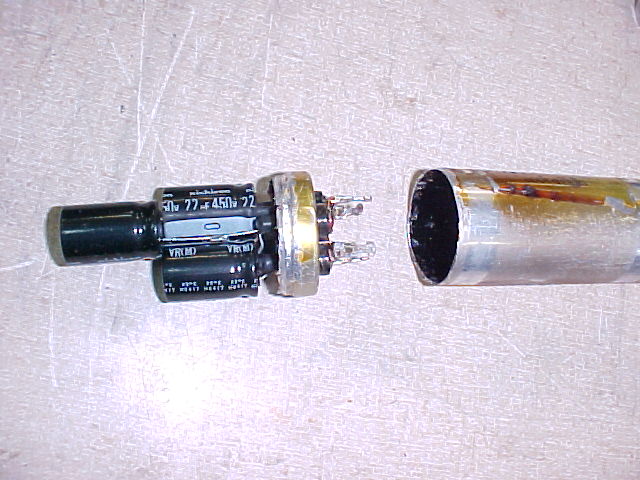
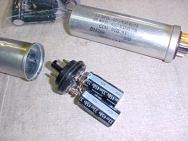
100mf @ 200v, Nichicon brand, are 16mm dia. x 31mm high
22mf @ 250v, Nichicon (or Vishay) brand, are 12.5mm dia. x 25mm high
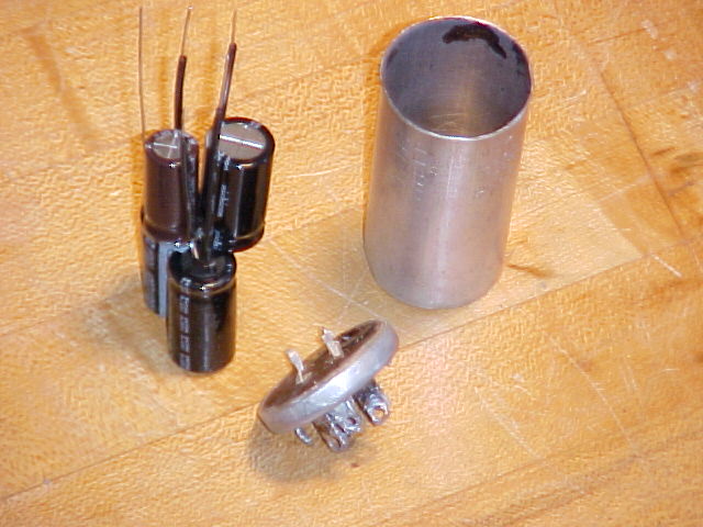
The 16m dia. is too big to allow 3 caps to be put side-by-side, but the length will allow 2 to be stacked.
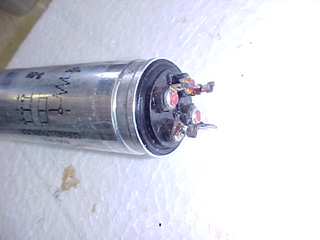
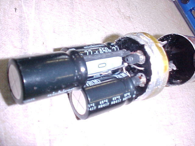
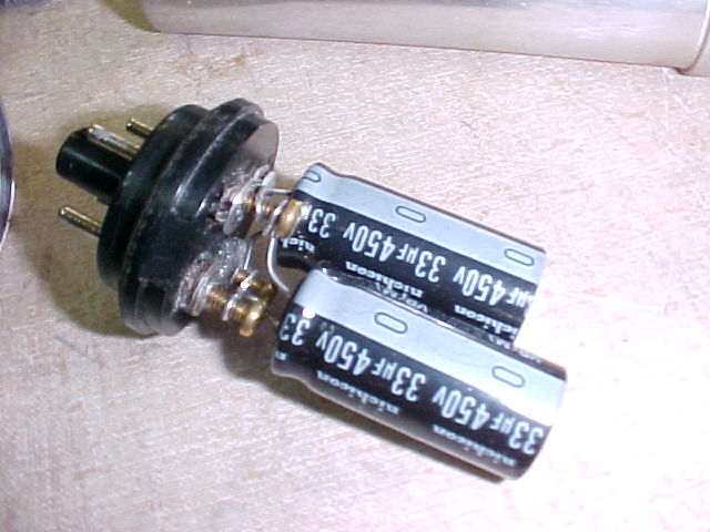
The negative leads were formed together and soldered with a #20 bare wire, the positive leads had a #20 lead extension soldered on, with shrink tubing placed over them.
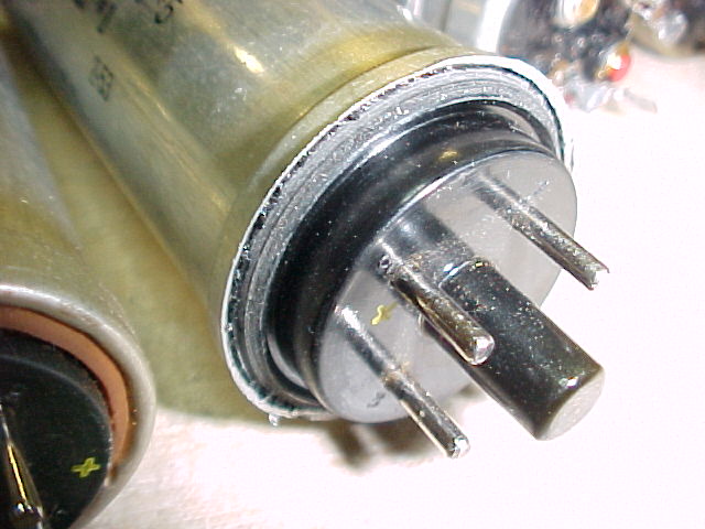
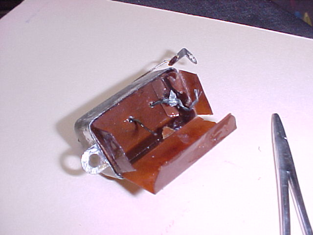
The terminal end of the can was drilled next to the existing terminals for the #20 leads, as the leads inside the original filter were aluminum, and were staked or welded to the copper terminals. The #20 leads were then solder to the existing terminals, and the negative lead was soldered to the can. A stranded lead was soldered to that point to be later soldered to ground inside the receiver.
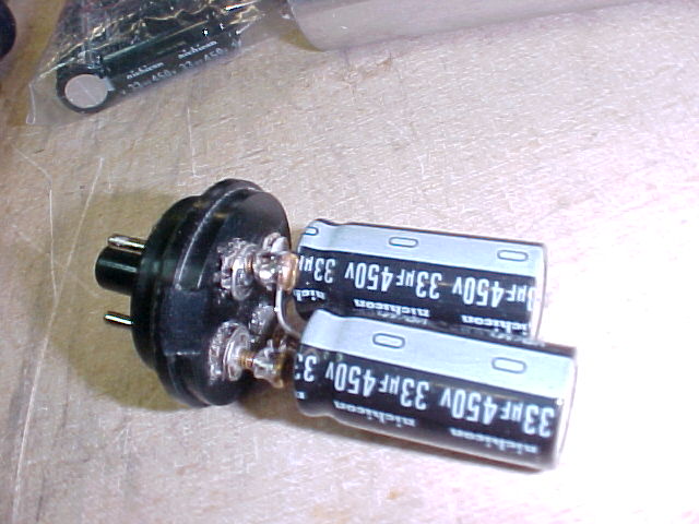
Epoxy was then used to re-seal the unit.
I hope this will encourage others to do the same. It's not a hard procedure, after the cans are open, less than an hour of work will give a new multi-section filter capacitor.
Al, W8UT
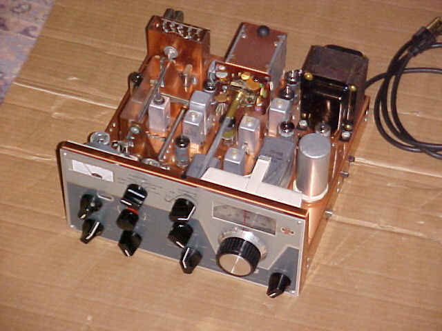
here's a shot of the receiver with the "new" can installed.
see update, Jan. 13, 2004 for info on the Drake AC-3 power supply caps

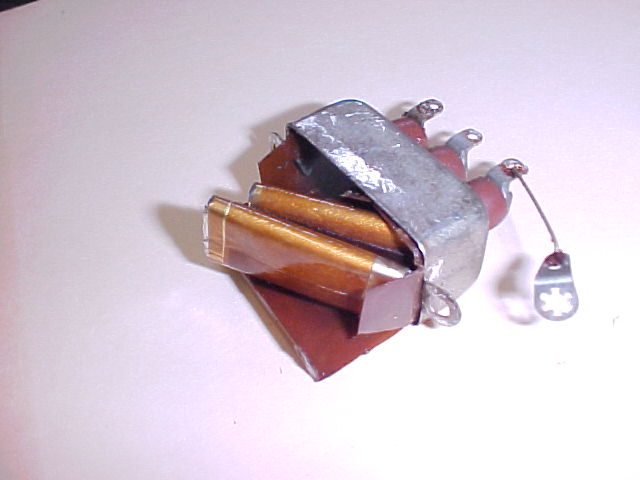
I cut the cans apart as shown. I used a lathe, it can be done with a razor saw or even a tubing cutter. The insides come right out of some of them. I had to use some heat from a propane torch to slightly soften the inside material (ukumpucky is the term often used). They all came out in one cylindrical "lump," not as a messy goo. The aluminum leads to each section are easily cut to leave the cap with terminals, and the remains disposed of. The cans should be cleaned inside, there's a little residue on the sides. I used kerosene. It helps to make a V-cut just above the larger diameter boss at the bottom. The terminal end is drilled for the 4 wires to be soldered directly to the terminals on the outside.
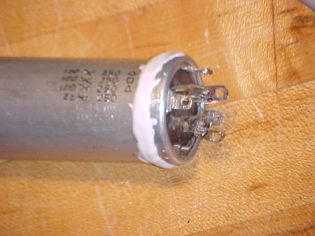
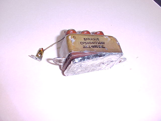
The R-388 is slightly different. If the end is cut properly at the bottom it may be possible to just crimp the large diameter over the end of the plastic terminal base to close it. The end can't be drilled for wires to be soldered to the pins on the outside, it would be messy looking and wouldn't fit nicely in the socket. So, the inside posts (aluminum) are drilled and tapped, and short 4-40 brass screws are inserted, tightened, and the wires soldered to them.
If you don't want to do it yourself, I can rebuild your SP-600 or R-388 capacitor, or supply one an exchange basis, for $20, plus postage.
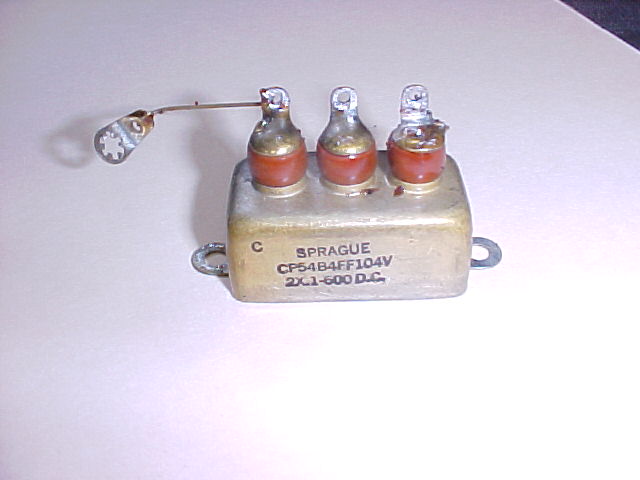
"Bathtubs"
More of the same for bathtubs. Lathe or cutting work is not necessary, just hold the tub with grips, and heat quickly with a propane torch. Rap it on the floor when the solder is molten, and you may be lucky enough to have all the solder out of the gap and a little prying will remove the bottom. Remove the old capacitors, solder the replacements in directly, tack solder the bottom back on.
<<<update, Jan. 13, 2004>>>
Mark, K9MRK, has just searched for suitable capacitors for re-capping the AC-3 & AC-4 power supplies. He realized the space problems and has come up with the following source, with approx. prices as of this date:
Mouser carries Nichicon electrolytics which are considerably smaller than
others.
By "considerably smaller" I mean they fit and the others don't.
For what it's worth here's my parts list for Mouser:
2 647-UVR2C220MPA
22uf/160v .56
2 647-UVR2C101MHA
100uf/160v 1.57
1 647-UVR2V101MHA
100uf/350v 2.77
2
539-CGS450V140
140uf/450v ~12.00 (just went up)
2
539-VR3
1-3/8" clamp .83
I substituted 140uf for the 125uf caps and 100uf for the 80uf.
Good news is the 140uf Mallory caps fit right and look good in place of the old
125uf caps. Bad news is there is no way to use the clamps as-is because
they are physically too close in the AC-3 at least. I cut the tabs off the
clamps with a Dremel cut-off wheel and used a couple heavy cable ties to
compress the clamp along with some hot melt glue to insure they can't slip or
rotate. As they have screw terminals you'll need a few uninsulated
terminals to rewire them (the neg side is not to ground!).
The other caps I essentially cut off leaving the base without even removing them
from the chassis with a hobby saw and fine hacksaw blade in tight spots. Then
filed the 'stumps' down to clean up the surfaces and remove any burrs.
Then drill small holes for the radial leads, install the caps and solder to the
old existing lugs. Not very original but clean looking and you don't have
to desolder the existing connections and no exposed HV. Also if you remove
the paper covers off the old electrolytic they will slip over the new caps and
even without replacing the cans look pretty original and make it easier to
service (in another 40 years). It's fast and easy to do and appears that
you could epoxy/hot glue the cans over the Nichicon caps if you desire.
Thanks to Mark, K9MRK for this info
comments to anchor@ec.rr.com
And remember: "They don't make tubes nowadays like they used to..."
This page last updated on 06/18/2005.