
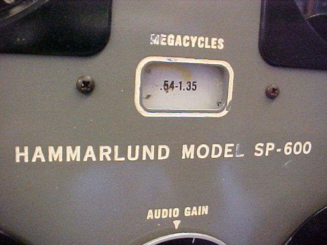
SP-600-JX-10 s/n 6363
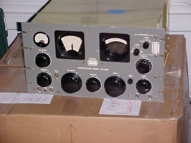
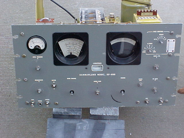
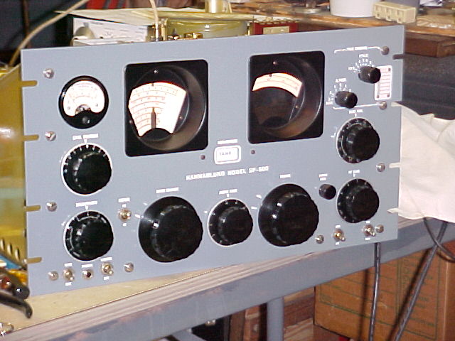
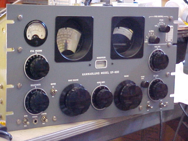
SP600-JX-10 s/n 6363 arrived 12/10/02 quick pix as received, click on thumbnails for full size
will add initial observations later
Initial inspection, 12/28/03
General notes: (click on thumbnails for full size pix)
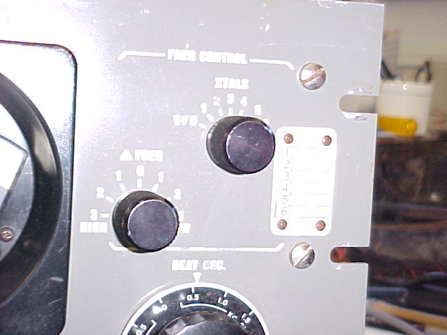
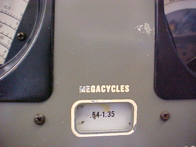
Has been MFP'd, very heavy, non-uniform coating, much flaking on side panels, many small "globby" spots, many small areas where some corrosion has started. Has top cover and all tube shields (1 with MFP removed), large 5R4WGA w/o hold-down, spare fuse cover (cracked), all tuning hole plugs, No xtals in FCU sockets, no cover for FCU switch.
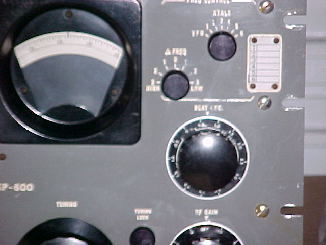
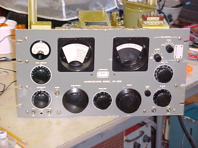
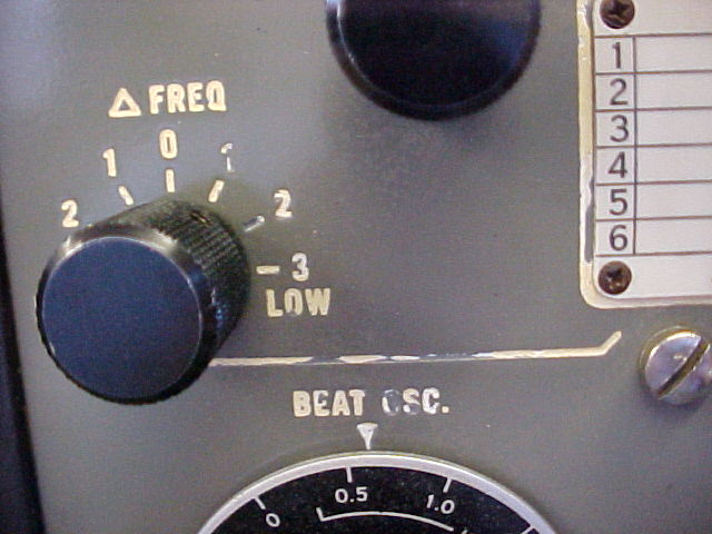
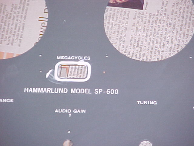
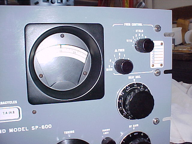
Front panel - some scrapes and local corrosion along top & bottom edges, one area of corrosion to the left of the B.S. dial bezel. Some lettering is losing it's paint fill, needs to be re-filled (all). Panel hardware is shiny, but has screwdriver damage in slots. Dial faces are good, probably just cleaning will make them very good. Dial bezels have small spots of missing paint, showing brass. Meter is not at zero, won't adjust properly.

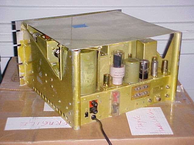
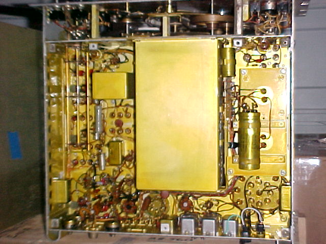
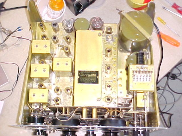
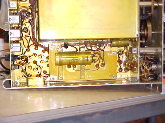
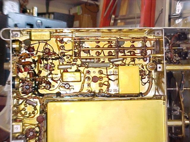
Top side - 4 screws missing from turret top cover, RF deck has been off, good solder job on reconnections to variable cap. Mirror inspection reveals disc ceramics in RF deck, some new wires & at least 1 new resistor. T-2 pod has been off & probably recapped.
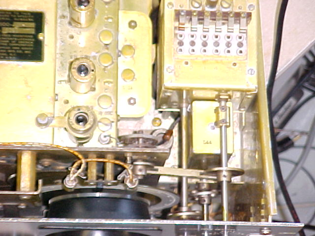
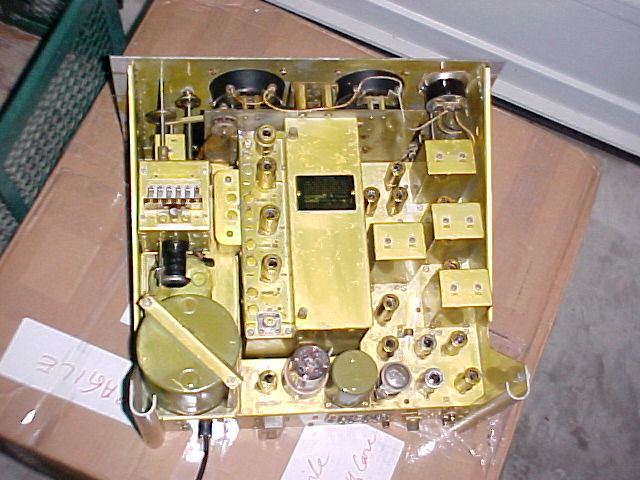
Under chassis - Orange Drops and disc ceramics are in place of all paper BBOD's under chassis. AC line input is to 117v tap on transformer, will switch to 125v tap to lower voltage. Filter cap ESR test shows sec. 1 = 1.2ohms, sec. 2 = 1.4, sec. 3 = 1.6. Later, after being powered up for about an hour there is no warmth on the filter cap can, so it is not necessary to replace it (can be done if desired). Gear train is clean, but dial drive tends to slip. C-158, -9, -60, 10mfd ea., in the bias line have been replaced at some time, they do not have any MFP.
Powered up - used variac initially as history not known. It came to life at about 85VAC input. Kept at that for about an hour, increased to 120v. All bands are operable, S-meter is not generous, actually kind of stingy. Measure ~365vdc to filter section, -53vdc & -11vdc on the bias lines vs -51 & -10 std, OK. Good audio output to speaker thru a 600:8 transformer, and from diode load to external amp.
12/29 - 1/3/04
Work progress - Changed AC line input to 130v tap on pwr xfmr to
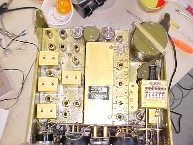
reduce voltage on secondary. Removed tubes & IF cans, cleaned chassis.
It wasn't very dirty, the mottled, heavy MFP coating makes areas look bad. Checked all tubes, all good. 12AT7 was in
place of 12AU7, it tests good as -AT7, but weak as -AU7, will ck performance
when doing alignment. It's a dual triode used as low-level audio
amps. Waxed the knobs. The caps in the IF cans have been replaced,
all the re-cap work was done very nicely.
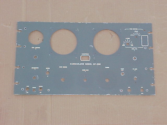
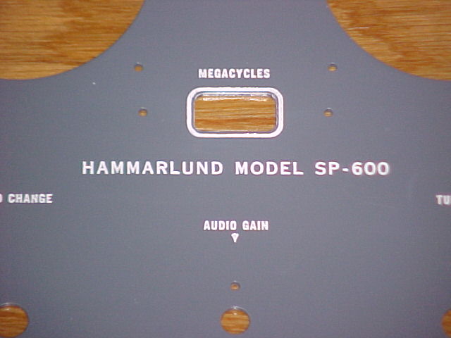
Removed panel, as a good finished appearance is wanted.
Took many pix to show areas of concern. (note that the color rendition
depends greatly upon the available light.)
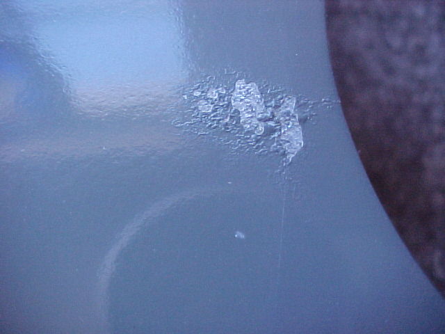
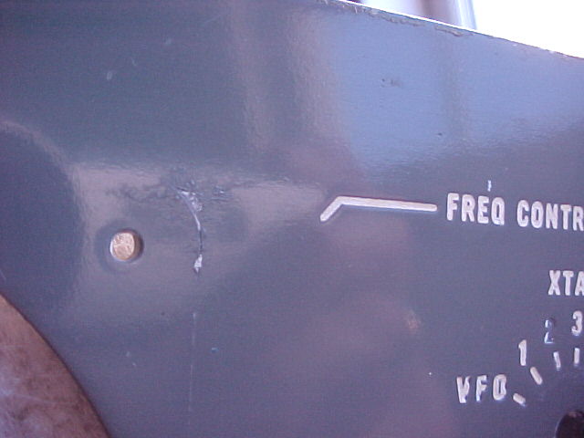
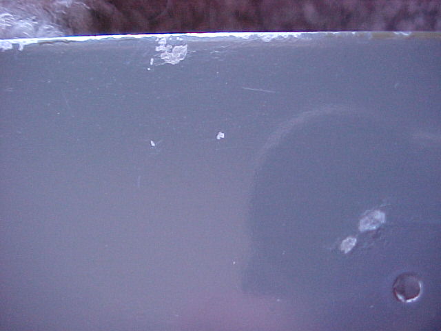
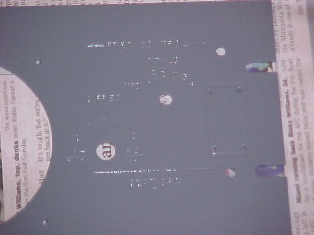
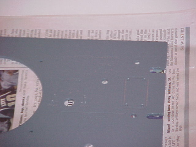
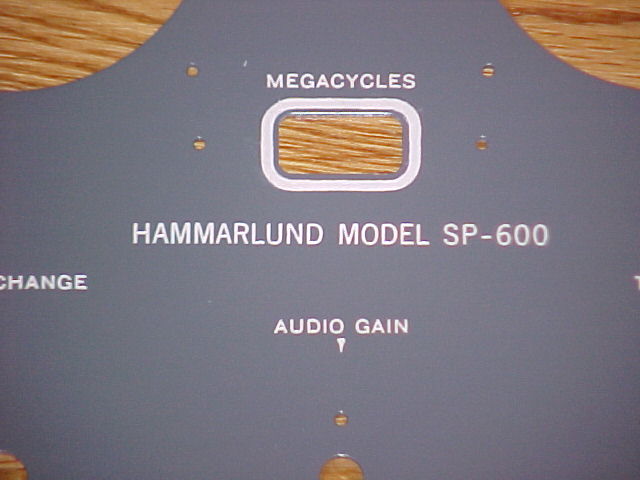
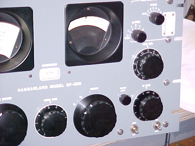
Overall view before cleaning (first 2) and after buffing with rubbing compound (all others). Note spot at the left side of the rt bezel. This is not just a scratch, it shows, as do the next pix, corrosion of the aluminum panel. If you look closely at the overall view you can still see the areas under the knobs & bezels where the paint was protected from light, etc.
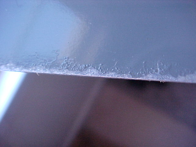
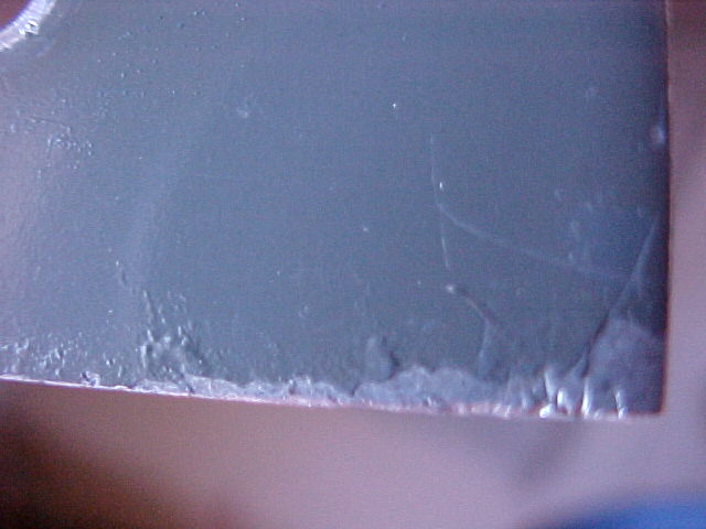
Bottom and top edges of panel. Initial look from a distance appears to be just scraped paint, but closer look shows corrosion extending underneath the paint.
Touch-up of these areas will not look good. The paint over the corrosion will flake off if not removed, and to remove it will expose larger rough areas which will need to be smoothed or filled. Paint match will not be perfect, and surface texture will not be uniform.
I'd recommend complete stripping of the paint, probably 2 prime coats, one fairly heavy, trying to hit the corrosion areas while missing the engraved lettering, and a second light prime coat. Wet sanding between to blend in & improve finish.
1/10-13
I opened up the meter & fixed it so it does read zero & can be adjusted. It's possible that it was mechanically kept from deflecting properly & seemed inactive or that the rcvr had low sensitivity. I'm not sure I can find the specs on it, but I will test it's full scale deflection current & resistance to see if it's in an expected range. I can ck another to compare if needed.
Later I did set up a test with this meter and another one. The good one has a full-scale current of 240ua, at 120mv, for a resistance of 500 ohms. This one has the same resistance, but does not deflect full-scale until well over 300mv, and is erratic at that, not reaching the same reading for the same current each time. It reads about 40 to 60 db low at mid-range on the RF level scale, compared to the good meter. According to the schematic, full-scale should be 200mv. This explains why we thought the receiver lacked sensitivity, the meter wasn't as sensitive as it should be. I feel that this is due to damage to the spiral hair-springs, coils may still be overlapping or deformed. I'm not a meter repairman, this needs "microscopic surgery" for repair. The meter operates, it's just not sensitive. The case has been repainted by a previous owner, it may have been damaged at that time.
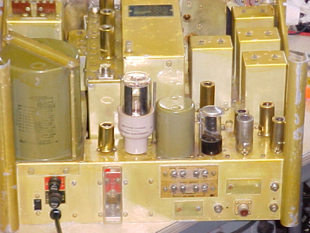
Much later, I spent some time understanding the AVC and RF
meter circuits. The RF level is determined by the detector, not the actual
AVC voltage. A DC voltage proportional to the signal is developed by the
detector, and is impressed upon a voltage divider string of resistors. The
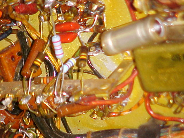
meter is tapped into this string. One resistor, a 22k, had been previously
replaced, it's the upper new one in the pic. It is below the meter tap-in
point. The other new one in the pic was replaced by me, it should have
been 47k, it measured 61k after removal. It is above the meter in the
divider string, and at 67k vs 47k, would serve to reduce the voltage seen by the
meter by about 10%.
This bad 47k resistor, plus the fact that the meter has a full scale deflection of
over 300mv, vs 200 specified, resulted in the meter not reading properly.
Presently, with the new resistor, it does read nearly correctly at low signal
levels, but is very non-linear at stronger signal levels. A 50mv level
does deflect the meter about 1/4 scale, and corresponds to a fairly strong local
broadcast signal. A stronger signal will move it further, but when that
stronger signal diminishes, the needle won't go down until the signal is very
low. The hairspring must have turns that are hanging up.
The panel will be repainted, but will have to wait until the weather warms up a bit. It's been near 40-45F max in the days lately.
2/05/03 Weather and travel have slowed progress for several weeks
Panel progress - The panel has been stripped and sanded,
had 2 coats of primer and 2 coats of finish paint. Mild acid etch before
each coat, bake and wet sand after each coat, but no wet sand for the final.
I've got a makeshift oven that gets things up to about 150F, so it comes out
quite hard and durable. The corrosion shown at the panel edges, above, is
undetectable now.
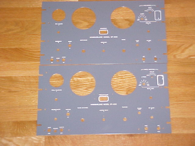
I did 2 panels at one time, these
pix may not be of s/n 6363, although they are marked on the back so I know which
is which, and s/n 6363 still has MFP on the back.. The engraving was slightly different between
the 2, see below.
top
corner before filling the lettering
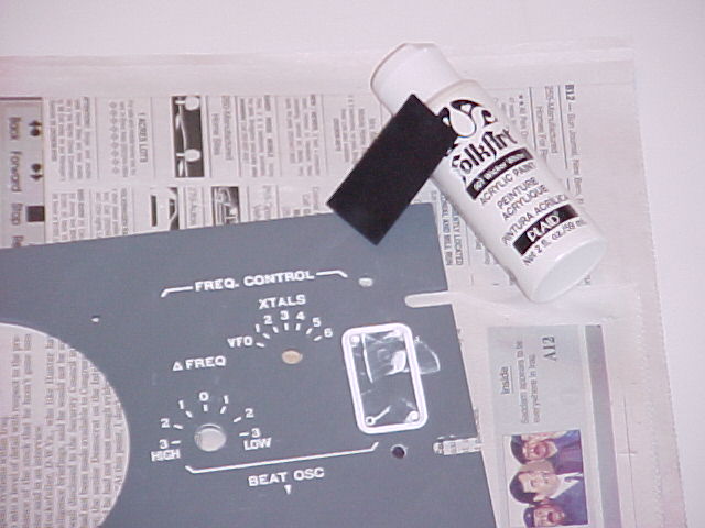
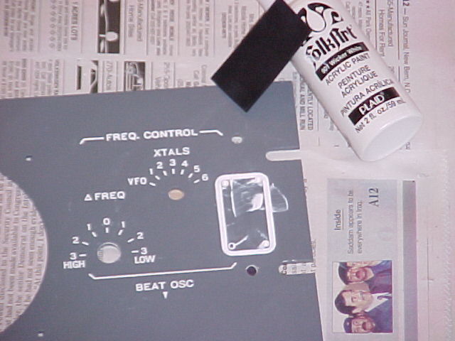
after
filling, showing the paint used, and the small neoprene squeegee for getting the
paint into the engraving. These area are the most difficult, with the
wide borders, which seem to be not as deep as the lettering. These pix
show re-touching in progress in those areas.
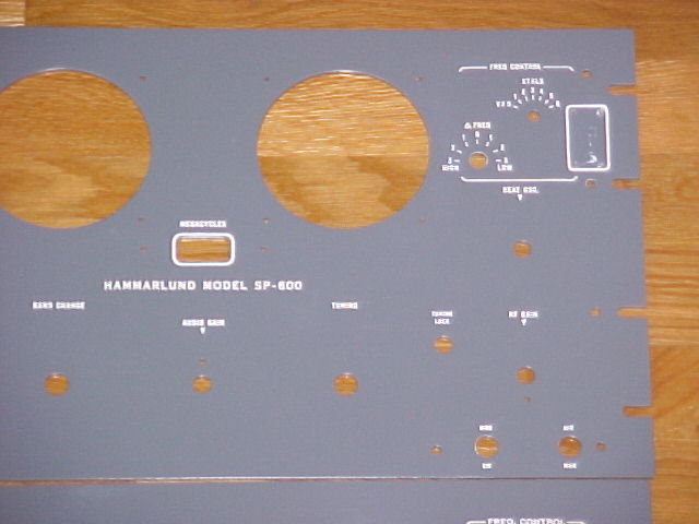
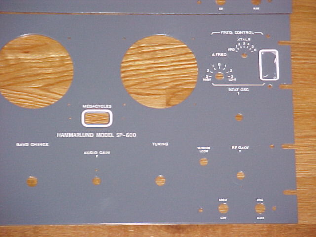
Here's a comparison (contrast?)
of the 2 types of letter engraving
The upper panel is from -JX-10 s/n 6363 and has the narrower boxes
and wider letters.
The lower is from an R-274 which did not have a s/n tag.
-JX-10
R-274
-JX-10
R-274
2/06/03 Completed panel installation
Different lighting and distance show different shades of gray. I don't
like the resolution, the lettering is much sharper than it appears. I'll
try some closeups.
2/10/03 Completed full alignment, check AVC voltages. Meter does have a spring problem, it's not smooth at about 1/3 scale.
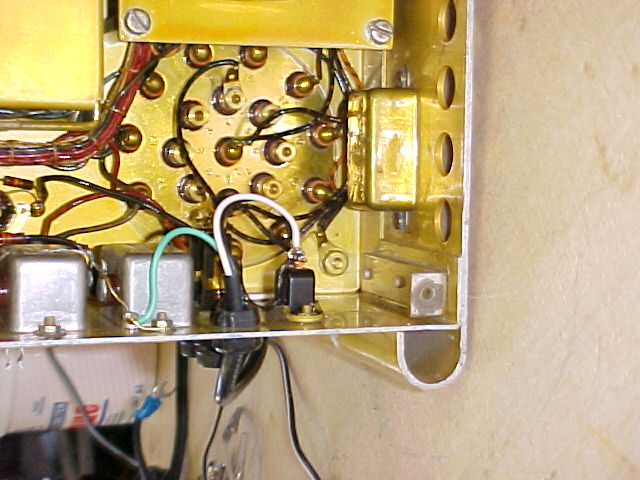
2/13/03 checked all "bathtub" caps under chassis, the 3 in the AVC/bias voltage supply had been changed by a previous person, they do not have MFP coating. There are 4 in line next to each other, the 4th one was bad, very high equiv. series res. It's the cathode bypass of the audio output tube. Replacement makes the audio much crisper, more highs. Very obvious looking at the scope while switching caps. I left the original bathtub in place, disconnected, and put a small electrolytic right at the tube pins.
2/17/03 I did a lot of listening (again), and general checking of voltages and resistances. Made a calibration chart for all bands. I'm still not happy with the AVC. I believe we should see more AVC voltage generated on strong signals. At first I thought it was just that the meter was not registering properly, but after some more measuring, I'm not sure. I'll do a little more "poking around" before I decide this one's finished.
| Frequency, kc |
Log setting |
Frequency, mc |
Log setting |
Frequency, mc |
Log setting |
||
| 600 | 074.9 | 1.5 | 068.8 | 4.0 | 108.1 | ||
| 750 | 204.5 | 2.0 | 235.2 | 5.0 | 262.5 | ||
| 900 | 315.6 | 2.5 | 372.8 | 6.0 | 402.1 | ||
| 1050 | 413.1 | 3.0 | 487.5 | 7.0 | 530.0 | ||
| 1200 | 500.9 | 7.3 | 567.5 | ||||
| 1300 | 554.7 |
| Frequency, kc |
Log setting |
Frequency, mc |
Log setting |
Frequency, mc |
Log setting |
||
| 8.0 | 063.7 | 16.0 | 062.5 | 31.0 | 117.2 | ||
| 9.0 | 149.1 | 17.5 | 124.7 | 35.0 | 201.1 | ||
| 10.0 | 230.9 | 19.0 | 185.8 | 40.0 | 303.5 | ||
| 11.5 | 347.2 | 21.0 | 265.5 | 45.0 | 404.0 | ||
| 13.0 | 458 | 23.0 | 342.1 | 50.0 | 501.0 | ||
| 14.0 | 528 | 25.0 | 417.2 | ||||
| 28.0 | 523.7 | ||||||
| 29.0 | 558.6 |
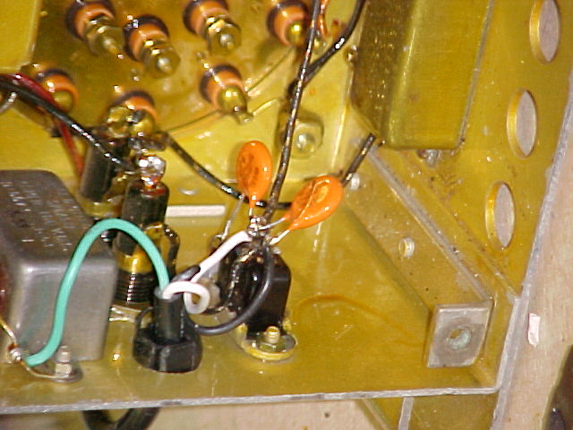
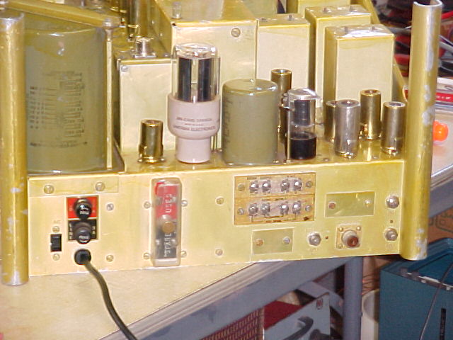
I replaced the AC line bypass caps that were "bathtub" style, with
250vac rated caps. The original is still in place, disconnected, it's
visible at the upper right in the pic. I also re-wired the AC line input
so that the fuse was the first thing in the "hot" side, vs the pwr
xfmr.
(see info at 1/10-13 for update on RF meter)
SP-600 return to SP-600 page
HOME return to home page