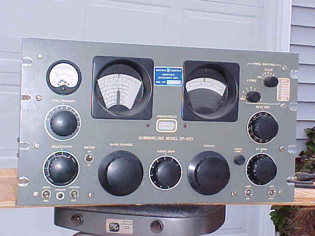
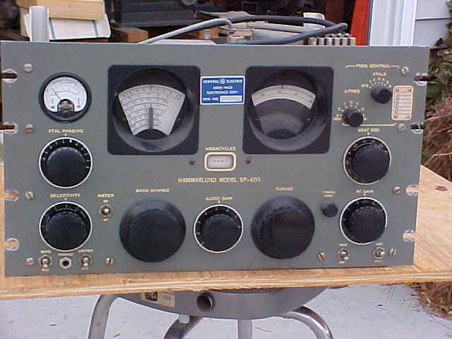
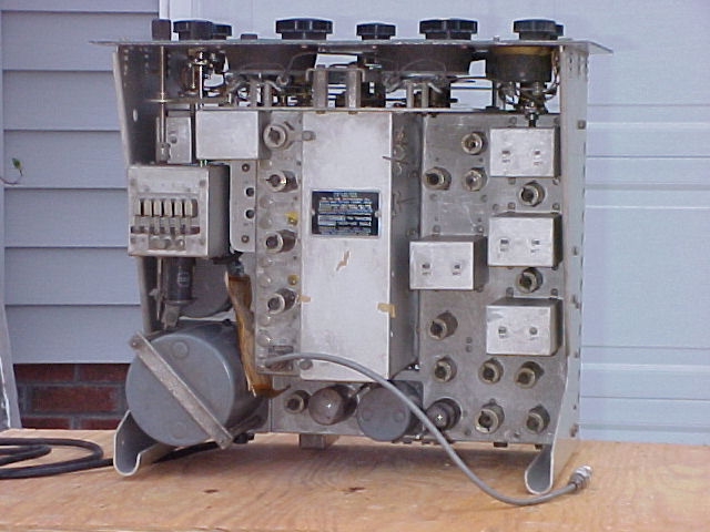
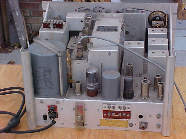
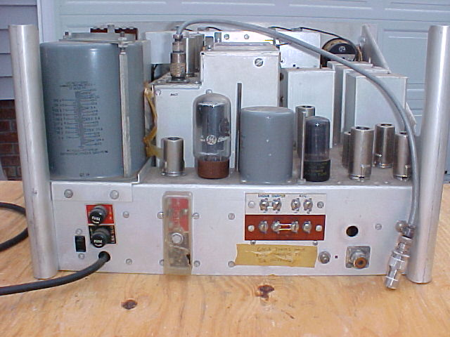
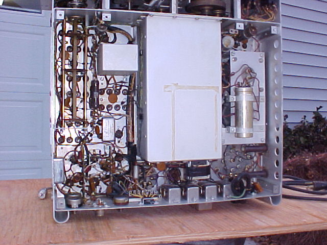
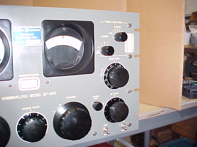
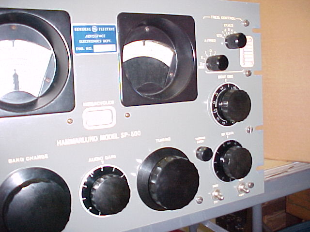
 pix taken Dec.02,'02 (click on thumbnails for full size, panel pix aren't
very good)
pix taken Dec.02,'02 (click on thumbnails for full size, panel pix aren't
very good)
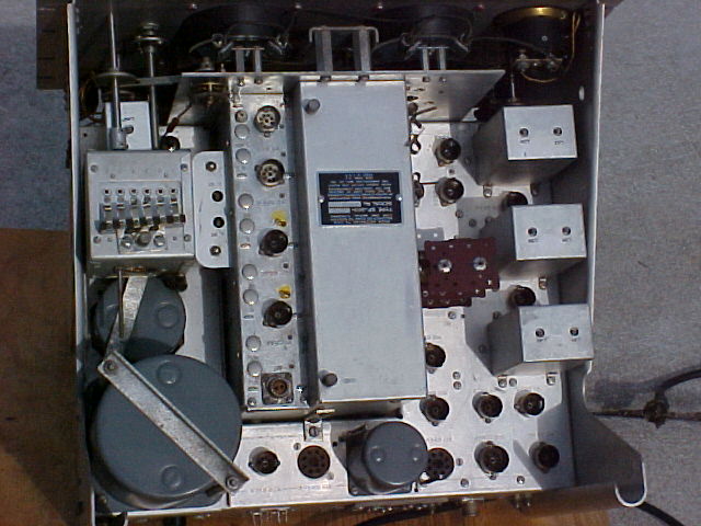
Initial observations:
12/3
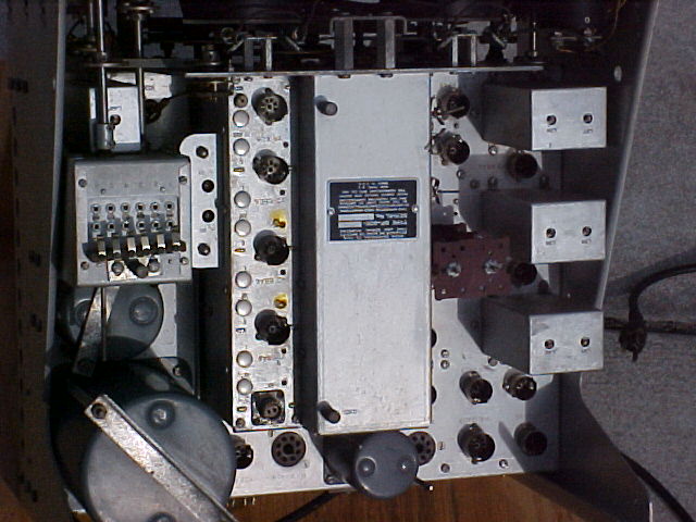
12/5&7
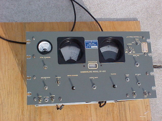
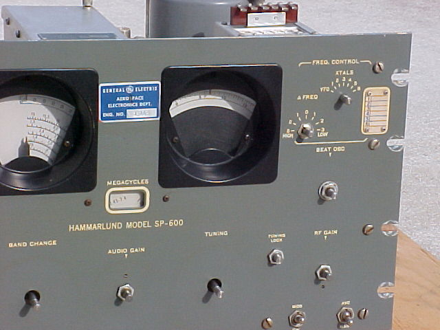
sorry the pix are so dark. ham fotog. I may lighten some of the better ones, later. or will take better ones inside, but hard to avoid flash flare .

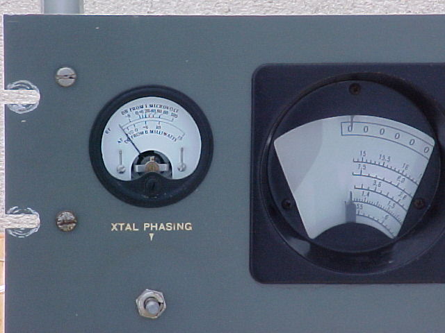
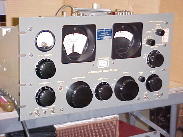
left bezel, before & after touchup
12/7-10
Knobs and front panel have been cleaned and waxed, chassis corners, nooks & crannies cleaned, as
have coil covers.
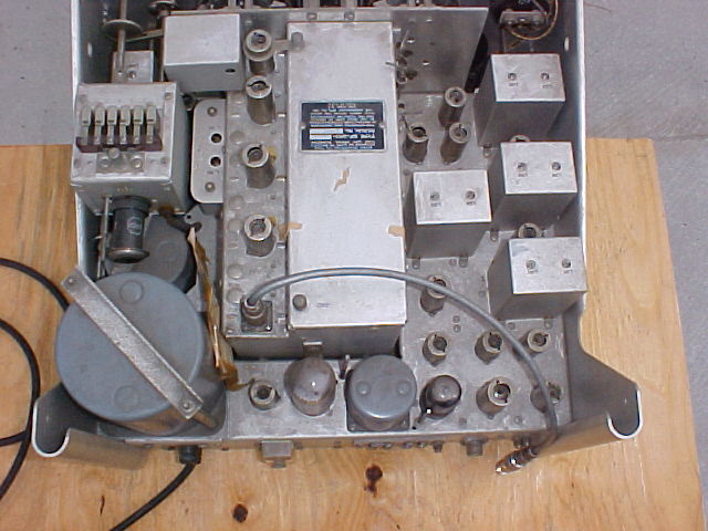
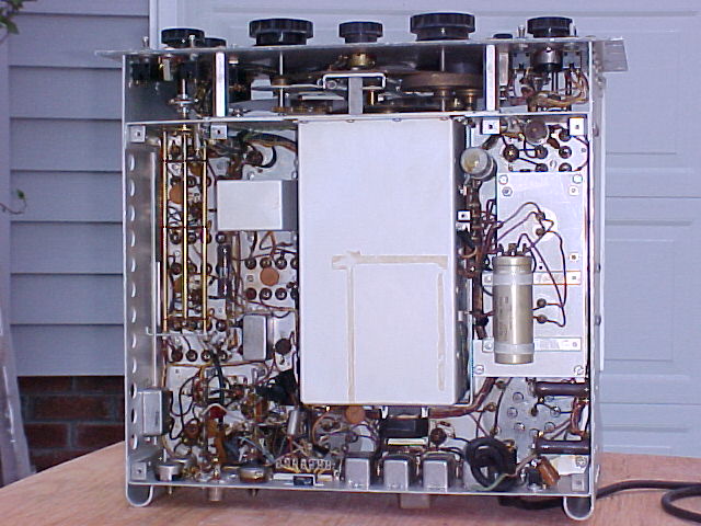
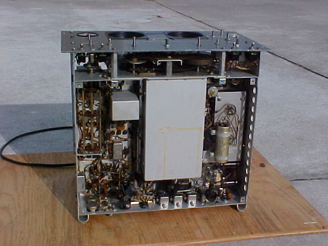
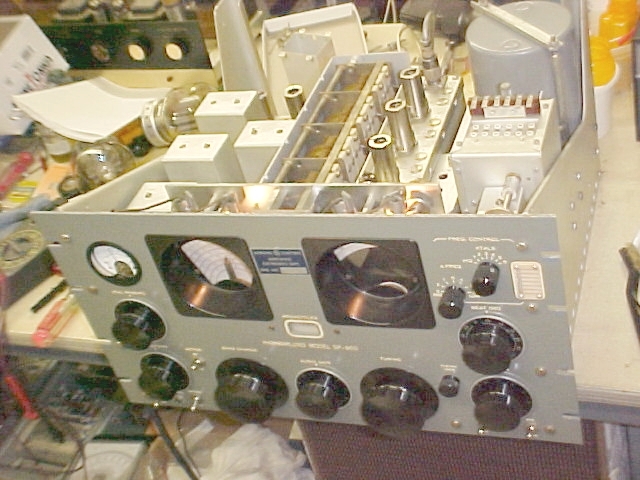
It looks clean enough, it's time to start back together. Still have
work to do under the chassis, but let's see if it still works.
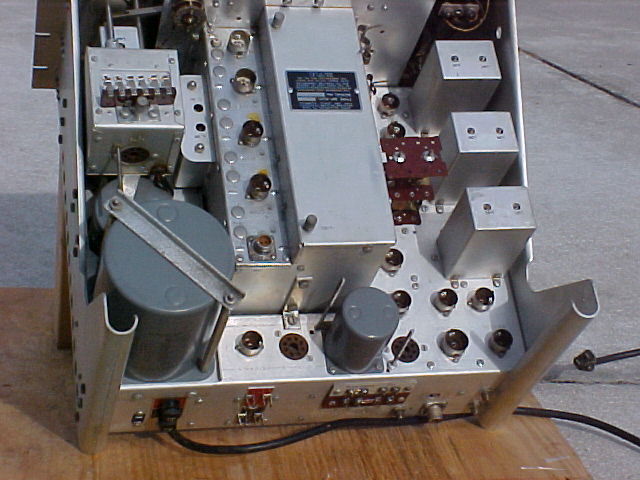
ready to go 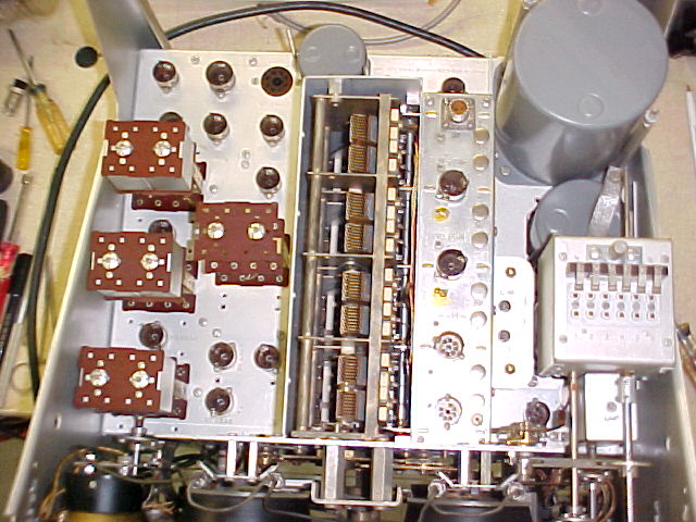 all in place exc. the turret cover
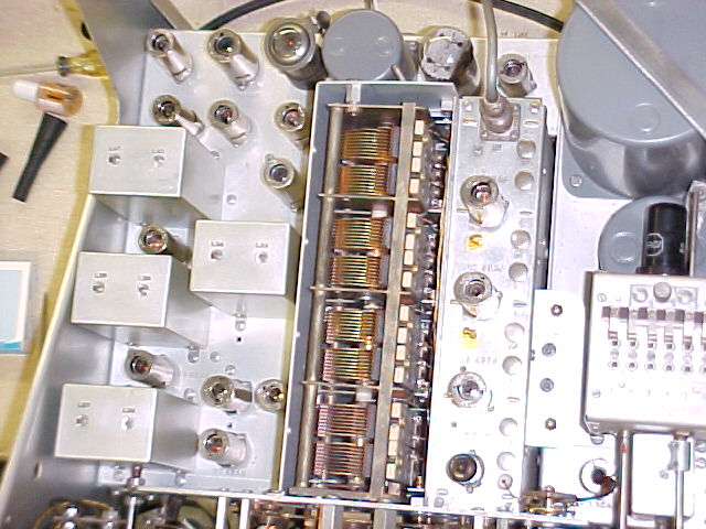
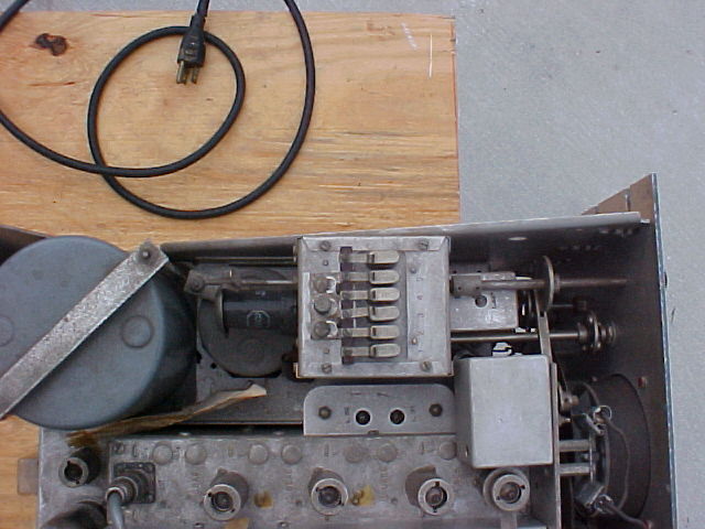
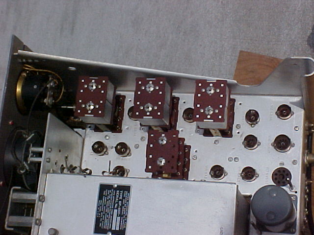
It actually started going back together yesterday
PM. I tested tubes, 1 6C4 oscillator is bad, the 12AU7 is low but usable, the 6AC7 on
the FCU, "extra" xtal osc., chassis showed a fil-plate short, I hoped
it didn't cause a problem in the osc. ckt, I wasn't planning on pulling it off
& apart, and planned to ck resistances at the tube socket. But today I
rechecked the 6AC7 when I was testing another as a replacement, and it doesn't
show the short. I had double ckd settings on the tester, don't know what
happened. I used DeOxit on the pins of all tubes as they went back in.
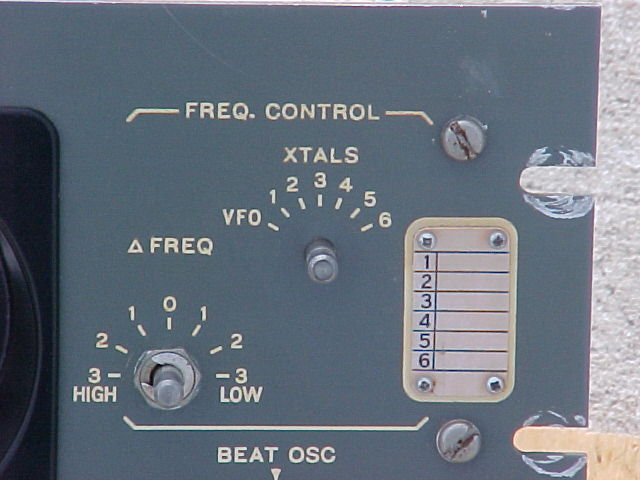
It's together, still works. WWV still there at 10 & 20mc, SSB signals copyable on 15m. The FCU is working with the original tube. I did make a chart of frequencies of the 6 crystals that were in the sockets. (non are particularly meaningful to me.)
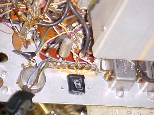
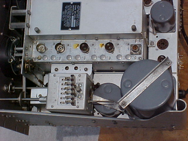
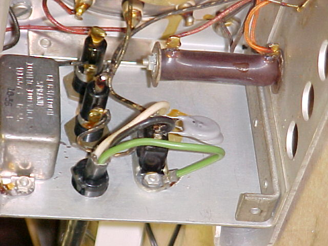
I think that mod on the terminal strip at the rear, with the little relay, is something to switch from getting audio output on the speaker terminals (normally) to output on the diode load terminals for an external audio amp. But it's got so many wires just hanging loose, I can't be sure. Will have to re-route 1 or 2 wires when I remove it, 'cuz they're going thru normally closed contacts now.
It's very stable. I've had it on a few times for
several hours since getting it back together, and after a short warmup period,
it stays right on the 14.300 Maritime Mobile Net freq. (SSB) with very little
attention for an hour or more. I removed the small mod. with the relay on
the terminal strip under the chassis. It had only 4 wires connected, and
apparently would remove audio, and all AVC, when activated. I don't know
it's purpose. I connected a tube type hi-fi amp. to the Diode Output
terminal, and get great audio from the local AM station playing jazz.
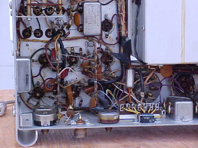
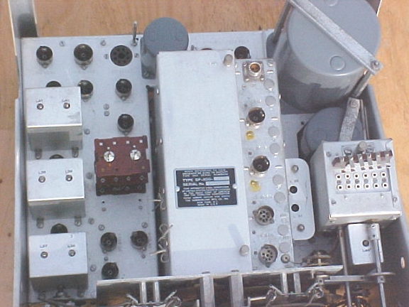
Next I will remove the small audio transformer that give 8
ohm speaker output (and no 600 ohm output), clean & DeOxit all terminals in
the turret, and perform a complete alignment.
Remove audio transformer, clean all (120) turret pins with 400 paper & DeOxit, align 455 & 3955kc IF's start RF alignment
Complete RF alignment, make chart of several bands' tracking accuracy. End points are right on, but some mid-points are off by 2 or 3 widths of the pointer, not a lot, but WWV isn't right on 10mc. 9mc & 13mc are right on. AMBC band seems right on, I hear a stn at every 10kc point.
the number "hi" is no. of pointer widths.
| Frequency |
Log setting |
Frequency | Log setting | |
| 3.700 | 057.8 ok | 10.000 | 235.5 2 hi | |
| 4.500 | 189.5 ok | 11.000 | 315.5 2 hi | |
| 5.500 | 338.4 2 hi | 12.000 | 391.0 1 hi | |
| 6.500 | 470.2 ok | 13.000 | 462.7 ok | |
| 7.200 | 557.2 ok | 14.000 | 631.8 ok | |
| 7.255 | 563.5 ok | 15.000 | xxx 1 lo | |
| 8.000 | 063.8 ok | 20.000 | 227.2 3 hi | |
| 9.000 | 150.8 ok | 24.000 | 384.5 4 hi |
Removed line cord & bypass caps in preparation for installing strain relief & new bypasses. Line cord insulation is badly cracked and it will be replaced. (there was no strain relief, the cord just went thru a hole in the chassis.
Enlarge hole for strain relief, install it & 2 new surge protection/bypass caps. Rewire AC input wiring to run the hot line thru the fuse and to the on/off switch, and put the neutral line to the transformer primary. Bypass caps are - 1 across the line, and 1 from neutral to ground, which I understand to be the proper configuration. Install new stainless steel fasteners, w/washers, to hold the panel to the chassis.
After I mix up and apply better matching touch-up paint, this unit will be
complete.
SP-600 return to SP-600 page
HOME return to home page